Keeping you up to date with the latest CorkSport Mazdaspeed news!
Category: MazdaSpeed 3
Mazdaspeed 3 was one of the most powerful FWD models Mazda ever built for production. It was turbocharged and had a 6 speed transmission and more torque steer than you could ask for.
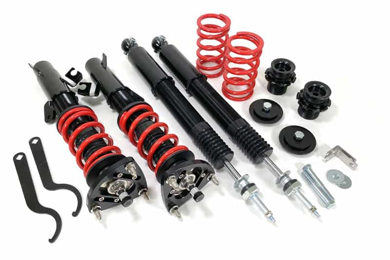
CorkSport Mazdaspeed 3 Coilovers are back and ready for your street and track Mazdaspeed 3 and Mazda 3! Taking the feedback from the previous generation of CS Coilovers and applying those to the new hotness has created a design that best balances performance for the street and track.
No longer using an inverted design, we opted for a more conventional, but performance-oriented monotube design with a pressure chamber. A monotube design was used for its superior damping response and precision vs a twin tube design. With that, we have increased the resolution of damping control from a 15-click range to a 30-click range giving you more fine-tuning control.
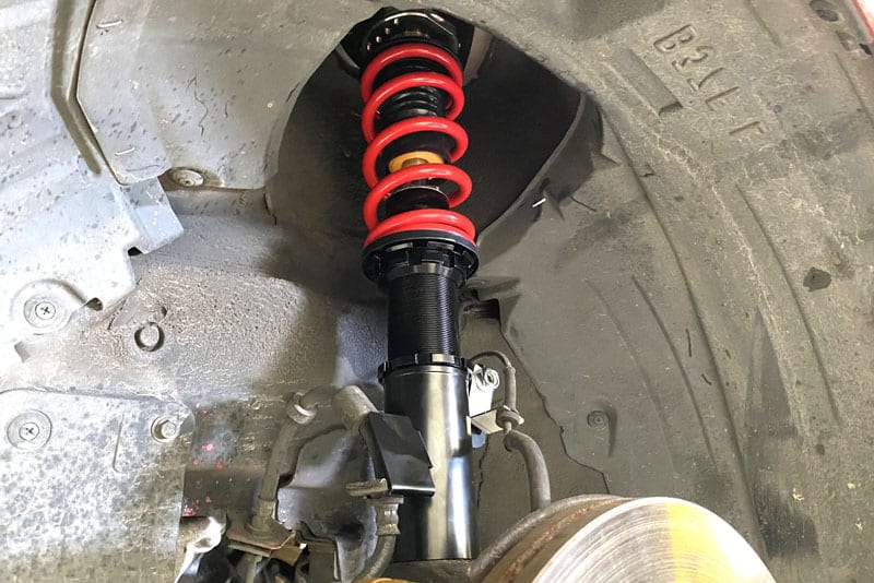
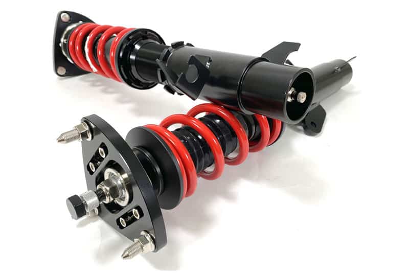
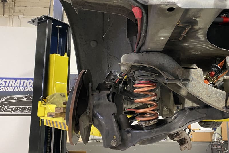
Installed Mazdaspeed Coilover with CS Springs
Next, the fronts now have independent spring load and ride height adjustability. This gives you the ultimate control in spring setup and ride height without affecting each other to do so. This helps to keep suspension travel optimized within the damper and makes adjusting ride height simpler.
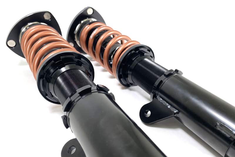
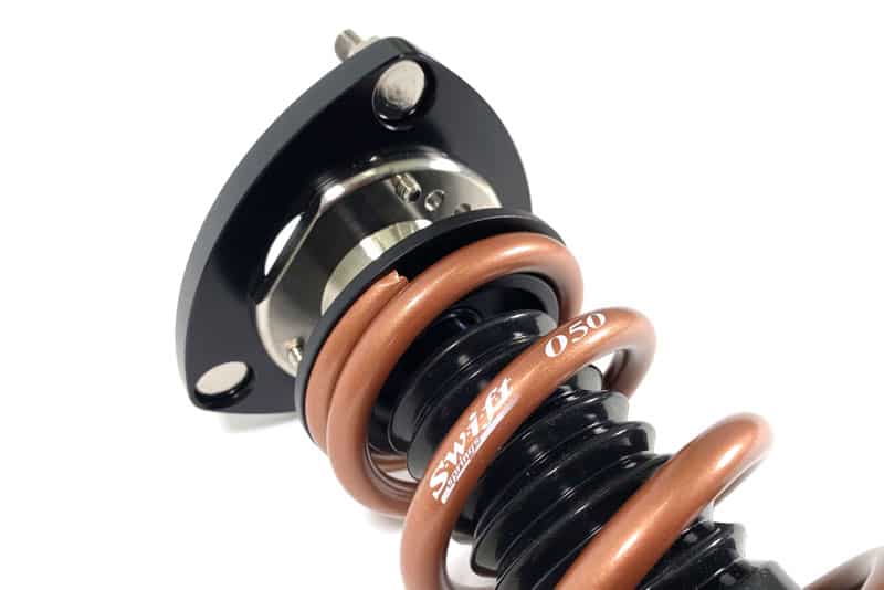
Swift Springs For Coilovers
Lastly, you may have noticed there are two different colored springs. We are offering two options for springs; CorkSport Red Coilover springs and Swift Spring upgrade. Even though there is no spring rate change for Swift, we still wanted to offer the option for those who swear by them. We suggest the daily driver opt for red springs and save money for some other goodies like Camber Arms, Toes Arms, or a Rear Swaybar. If you are wanting to push your car on the track, you may notice the Swift spring upgrade. Either way, you get to decide!
Talking about springs, we did “soften” the overall spring rates slightly per the requests of the community. For the balance of comfort and performance, we are using 6k fronts and 7k rear springs.
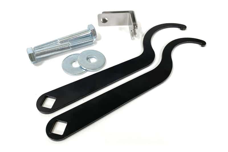
Now to the things that you already loved about the Mazdaspeed 3 Coilovers just get better! Included with the front strut assemblies are camber adjustable upper mounts so you can dial in your camber, wheels speed wiring harness brackets for OEM like installation and of course the needed rear hardware and adjustment wrenches.
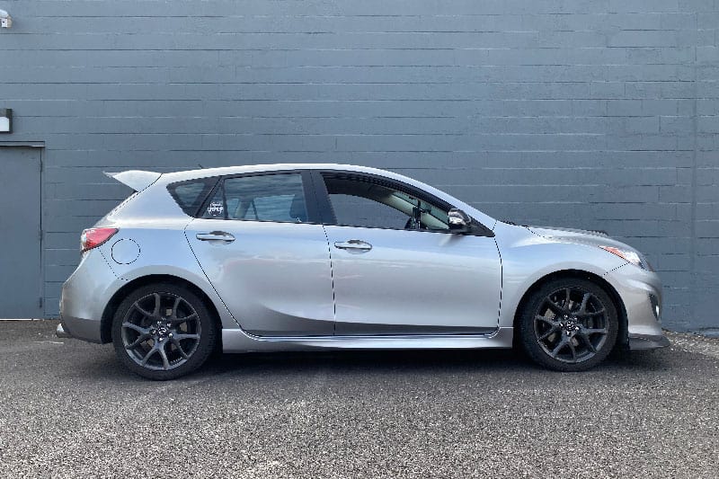
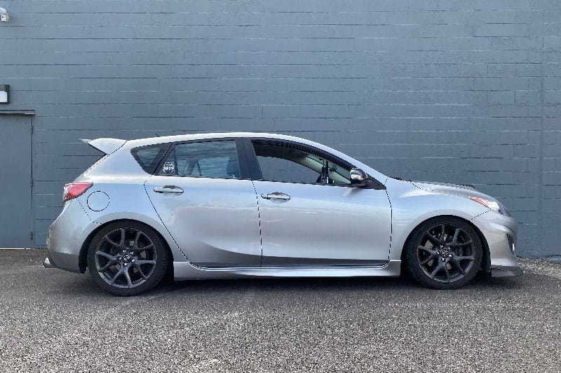
Now let’s chat about ride heights. While the CS coilovers are designed around handling, we can’t ignore the great visual boost that comes with lowering a car. The CS coilovers offer a large range of height adjustability. In the front, you can adjust the height from ~0.5” higher than OEM all the way down to ~2.0” lower than OEM (+0.5” to -2.0”). For the rear, you can go from ~0.25” higher than OEM all the way down to ~2.0” lower than OEM (+0.25” to -2.0”). This is 2.5” of total adjustability in the front and 2.25” of total adjustability in the rear.
Mazdaspeed 3 Coilover Maximum Ride HeightMazdaspeed 3 Minimum Ride Height
This is a great balance that allows for proper suspension function at low heights for those who want a stance look while also offering an OEM+ look for those that prefer a more subtle appearance. Don’t worry though, wherever you end up on the height range, the lowering does come with handling benefits as well, such as a lower center of gravity, decreased body roll, and improved driver confidence!
Welcome to part 4 of the Mazdaspeed3 AWD Swap! If you missed the previous posts, you can catch the Intro, (Part 2), and Part 3. This blog will cover the rear suspension design, specifically the rocker arms, and how we came to the size, shape, and overall design. This will get technical with numbers, angles, and CAD models.
Before we get into the technical jargon, let’s cover the “what” with rocker arm suspension.
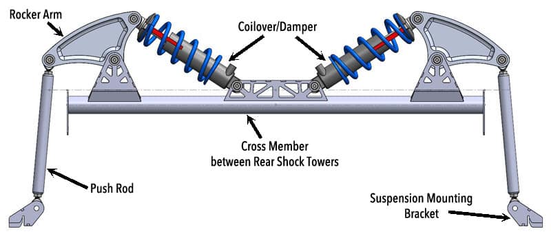
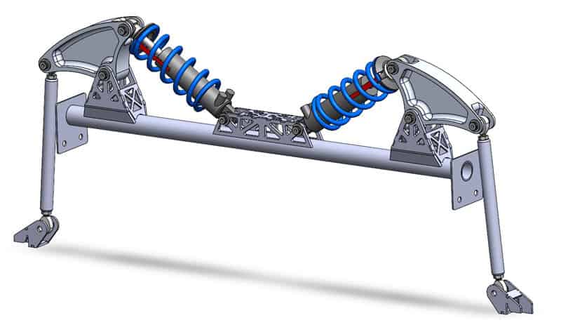
Mazdaspeed 3 AWD Swap Rocker Arm Suspension
Let’s break down this diagram as it is 100% not OEM for the Mazdaspeed 3:
Rocker Arm: This is the keystone of the suspension design and does all the work. The rocker arm connects the push rod and the damper to transfer suspension force at a different angle. The rocker arms can also go by a few names: rocker arm, bell crank, cantilever, and pivot arm, to name a few.
Push Rod: This is a simple rod with spherical rod ends on each end. This connects the OEM suspension to the rocker arm. The push rod is in a similar location as the OEM suspension.
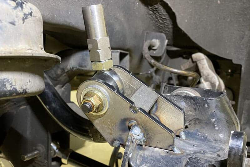
Suspension Mounting Bracket: This is the mounting point for the push rod to the OEM suspension trailing arm. This must be added because the OEM damper mount is below the now-new axle shaft.
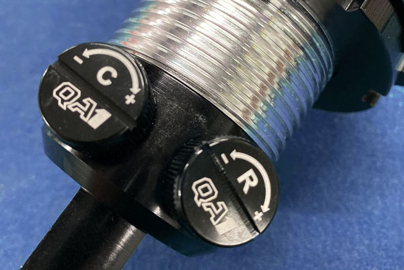
Coilover/Damper: This is an off-the-shelf damper that can have a coil spring installed on it. It features independent rebound and compression damping adjustability.
Cross Member: This is the cross member that is welded between the chassis shock towers in the car to support the new rocker arm suspension.
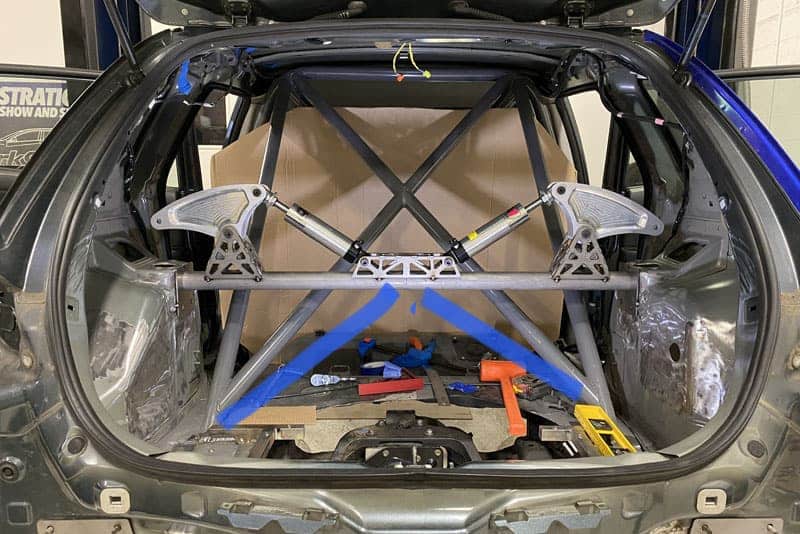
Here you can see the design tack welded in the car. This should help you understand how the design fits and is used in the car itself.
Mazdaspeed AWD Suspension Corss Member TackedMazdaspeed AWD Suspension Push Rod Mount
Now that we have a basic understanding of this rocker arm-style suspension let’s get into some more details!
First, let’s talk about suspension and the forces they deal with. Gravity pushes you and your car down to the ground, and road imperfections (bumps, potholes, unlevel surfaces) try to push you and your car up/down/all around while driving. If vehicles did not have suspension and instead the wheels were rigidly attached to the vehicle chassis, we would have all sorts of issues. Comfort, control, and tractions are the big concerns, amongst many others.
The suspension’s job is to soak up and move with many road imperfections like bumps, potholes, and unlevel surfaces. Every time your tire goes over a bump or pothole, it moves up or down, resulting in a force transferred into the suspension.
Check out this quick illustration to see the rocker arm suspension in motion:
As the tire moves up/down, you can see that the rocker arm pivots and transfers that motion into the coilover/damper.
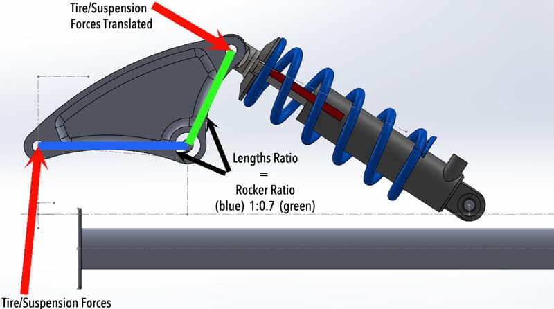
Now let’s break down those forces a bit more. The rocker arm allows us to change the angle of the forces transferred to a new angle that is easier for us to deal with. Instead of being required to have a coilover/damper in a vertical suspension down around the tire (like OEM), I can now change the angle so I can put the coilover/damper in a position that is much easier to deal with.
Rocker Arm Suspension Mazdaspeed Swap Forces
The rocker arm has two major features about it.
The angle change of transferred forces, as we just discussed. This is mainly to help with “positioning” the suspension components.
The rocker arm lengths allow us to define the “motion ratio” of the suspension. Looking at the diagram, you can see a blue line and a green line. These effective rocker arm lengths affect the suspension and result in a motion ratio.
The resulting ratio is 1:0.7 meaning the damper compresses 70% of the amount that the wheel moves up/down.
The wheel/tire has a maximum range of 5.55 inches of travel, while the damper has a maximum travel of 3.875 inches.
Designing the rocker arm with this 1:0.7 motion ratio allowed me to use a smaller, lighter damper design with limited travel and still get the desired wheel suspension travel I needed. We use a stiffer spring to compensate for the extra leverage of the motion ratio.
Motion ratios in suspension are common. For example, the Mazdaspeed 3 suspension has a unique motion ratio in the front (1:0.98) and rear (1:0.71) from our calculations. These numbers are typical of the style of suspension found in many commuter cars these days.
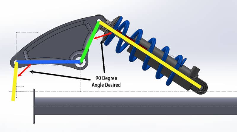
Now that we understand the forces and the intent with the rocker am…we have to design its shape and size to do the job. Angles are the tricky parts of the rocker arm design. Defining the angles (and thus shape) comes down to understanding the push rod input angles and the desired damper output angles while in motion.
Rocker Arm Suspension Mazdaspeed AWD Swap Angles
When we say “angles,” we are talking about the red arrows in the above diagram. These red arrows are the angles between the rocker arm and the push rod, as well as the rocker arm and the damper. Ideally, these angles are always 90 degrees through the entire motion you see in the GIF, but that is not physically possible, so we had to find the correct balance of angles while in motion.
A whole lot of math encompasses this, but the upcoming diagrams will help break it down to a very understandable level for everyone! We are breaking it down to the three major suspension travel points: droop, bump and ride height.
First, we are going to look at the angles for the push rod in Bump, Ride Height, and Droop.
Bump is when the suspension is fully compressed.
Ride Height is when the car is sitting stationary (static).
Droop is when the suspension is fully decompressed. Image your car sitting on jack stands with the tires hanging in the air.
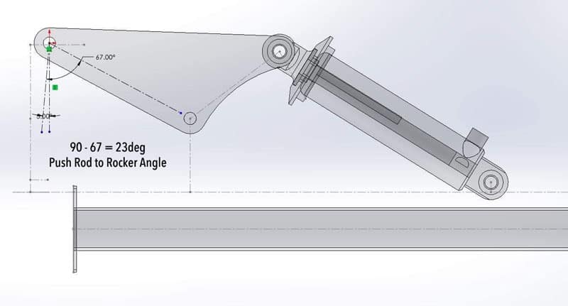
Mazdaspeed 3 AWD Rocker Arm Angle Bump Pushrod
In full bump, the push rod angle to the rocker arm decreases to 67 degrees which is 23 degrees off the “ideal” 90.
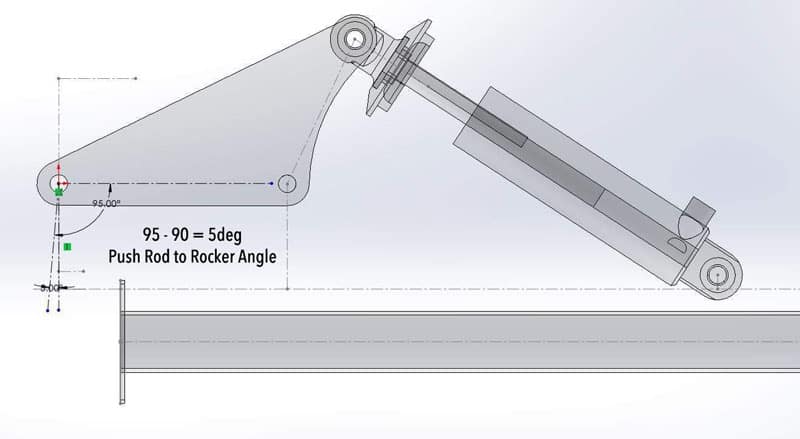
Mazdaspeed 3 AWD Rocker Arm Angle Ride Height Pushrod
Then looking at ride height as the suspension moves downward from full bump. The damper-to-rocker arm angle decreases to 82 degrees which is 8 degrees off the “ideal” 90.
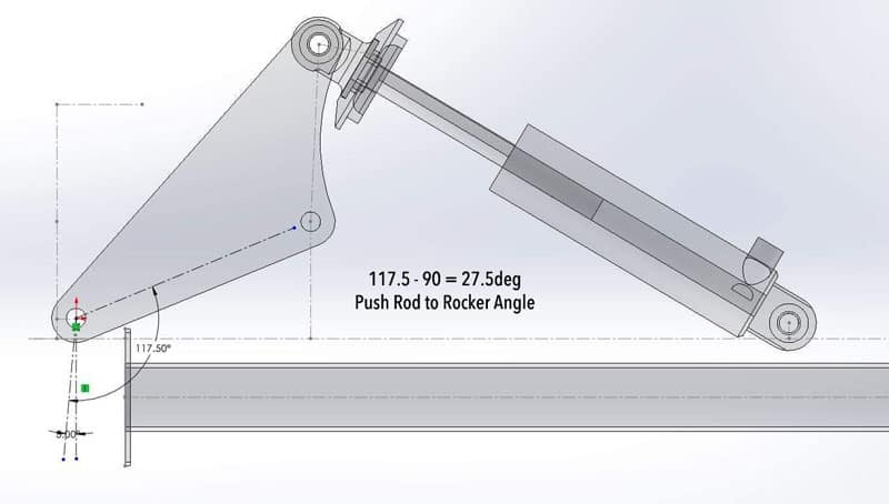
Mazdaspeed 3 AWD Rocker Arm Angle Droop Push Rod
Lastly, with the suspension traveling to full droop. The push rod to rocker arm angle increases to 117.5 degrees which is 27.5 degrees off the “ideal” 90.
What does this mean? This is great, actually! Ride height is where the suspension will function most of the time, and that is only 5 degrees off the ideal 90-degree angle. When the car is launched in a drag race, the suspension is going to compress, and that angle will decrease, passing through the ideal 90-degree angle and further. This is precisely the balance we are looking for with the rocker arm design. To keep it functioning most of the time as close to 90 degrees as possible.
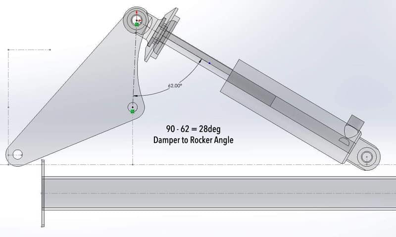
Ok, let’s look at the angles from the damper side of the rocker arm.
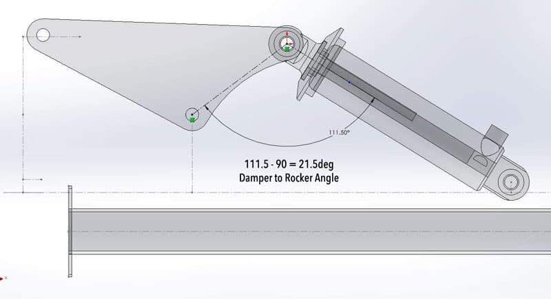
Mazdaspeed 3 AWD Rocker Arm Angle Bump Damper
In full bump, the damper angle to the rocker arm increases to 111.5 degrees which is 21.5 degrees off the “ideal” 90.
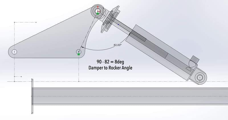
Mazdaspeed 3 AWD Rocker Arm Angle Ride Height Damper
Then looking at ride height as the suspension moves downward from the full bump. The damper-to-rocker arm angle decreases to 82 degrees which is 8 degrees off the “ideal” 90.
Mazdaspeed 3 AWD Rocker Angle Droop Damper
With the suspension traveling to full droop, the damper-to-rocker arm angle decreases to 62 degrees which is 28 degrees off the “ideal” 90.
Again we have the damper near the “ideal” 90-degree angle at ride height and then pass through the 90-degree angle zone when the suspension compresses at launch. Again, the balanced angles we are trying to design for so the suspension function in the “ideal” angle range most of the time.
Why are the angles so important? The further you get from the “ideal” 90-degree angle, the more non-linear the suspension acts. When the suspension acts in a linear function, it is tunable and predictable to drive. If it is non-linear, then it makes tuning and use much more difficult…this results in inconsistent launching and driving, which is not good in a racing environment.
Mazdaspeed AWD Swap Racecar Suspension
This seems like a lot of work…why do it?
A few reasons, really:
Moving to the rocker arm design gave me a lot of control over how I set up my Mazdaspeed for racing.
It also gave me the ability to use readily available off-the-shelf dampers. This allowed me to get double adjustable dampers (rebound and compressor) for a very cost-effective price.
The CX7 AWD swap rear axle shafts did not allow me to use the OEM dampers anyways.
This design moves more of the suspension component’s weight to “sprung mass” which is better.
I love the challenge of designing a suspension system like this, and this was a great opportunity!
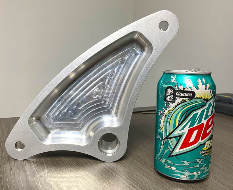
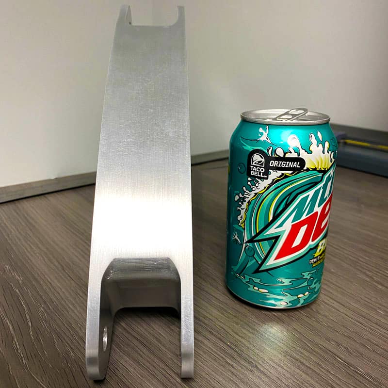
Before we wrap things up, note the rocker arms are 6061-T6 billet and are massive! We knew they were big, but it didn’t really sink in until we saw them firsthand.
Rocker Arm Size ComparisonRocker Arm Size Comparison 2
Alright, that wraps up the rocker arm suspension design, a huge novelty for the build. There are plenty more huge milestones to overcome, and those are coming up in this multi-part blog series!
I hope you are enjoying this series about the AWD Swap Mazdaspeed3, stay tuned for more blogs to come!
Welcome to part 3 of the Mazdaspeed3 AWD Swap! If you missed part 1 and part 2 blog posts, then catch up by visiting these links. Lots of images in this blog as I get the CX7 rear subframe installed and figure out the correct control arms to use for the rear suspension.
Typically when I mention the AWD swap Mazdaspeed 3 to a fellow Mazdaspeed enthusiast, they assume I am using the rear subframe from a Mazdaspeed 6. While I understand their logic, incorporating one would require extensive fabrication.
Here’s why: the Mazdaspeed 6 has a very different chassis architecture vs the Mazdaspeed 3. It is important to note because it directly affects the subframe and chassis interface.
If it’s not the speed6 then what do I use? Good news! The Mazdaspeed 3 uses a chassis design based on a Ford global chassis used with various models in Mazda, Ford, and Volvo. Enter the Mazda CX7.
Car AWD Hunt for CX-7 Subframe
So I went hunting for a Turbo AWD CX7 model year 2006-2007…this is a great time to bring your buddies along for some junkyard fun!
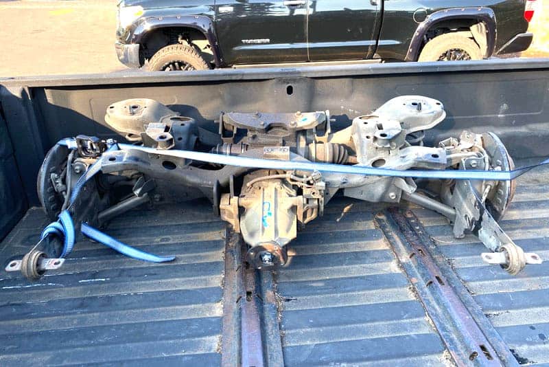
Luckily I found one in a local junkyard that was still complete enough. Not knowing exactly what I needed from the rear-end suspension and drivetrain, I opted to take everything; driveshaft to differential, plus the ENTIRE rear subframe and suspension.
CX-7 Rear Subframe
$380 later, we are driving home with our newfound treasure and ready to take on the swap! I was eager to see how this would bolt into the Mazdaspeed 3, so we went straight to the shop.
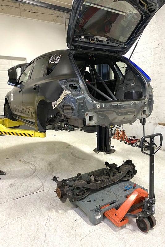
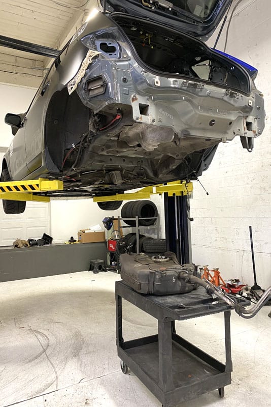
We wasted no time removing the speed3 rear subframe… literally six bolts and removing the brake calipers is all that is required.
Mazdaspeed 3 Rear subframe removedOEM Fuel Tank
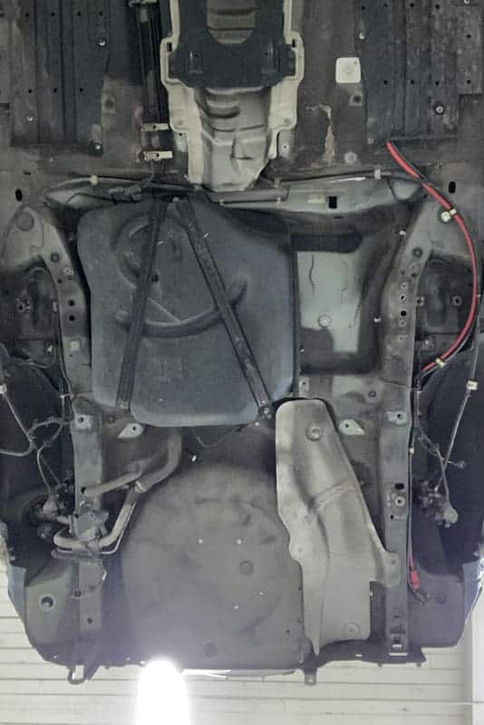
Knowing the OEM fuel tank is in the way of the mid-driveshaft, we opted to just remove it right then as well. A handful of bolts and some fighting of the fuel tank filler and it’s out also. At this point, we are maybe 1.5 hours into this and the car is ready to accept its fate.
OEM Mazdaspeed Fuel Tank Removed
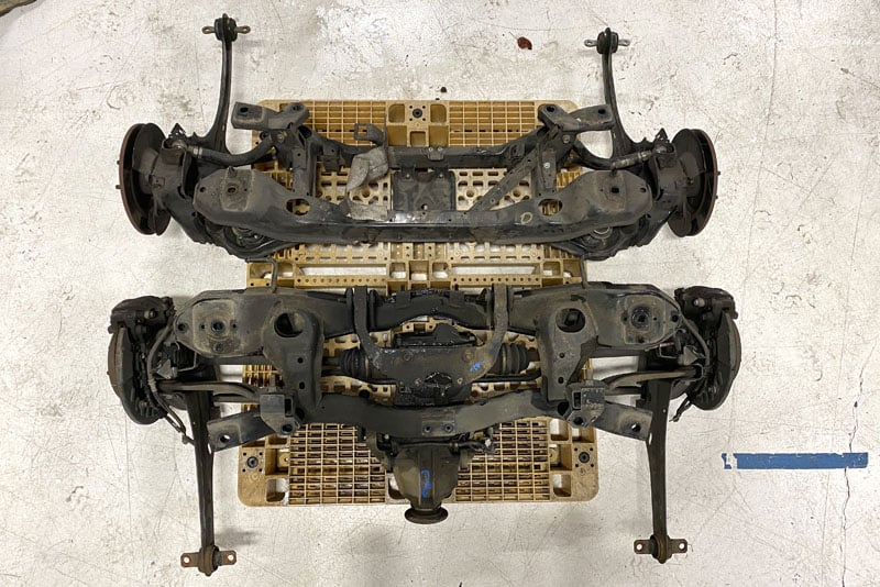
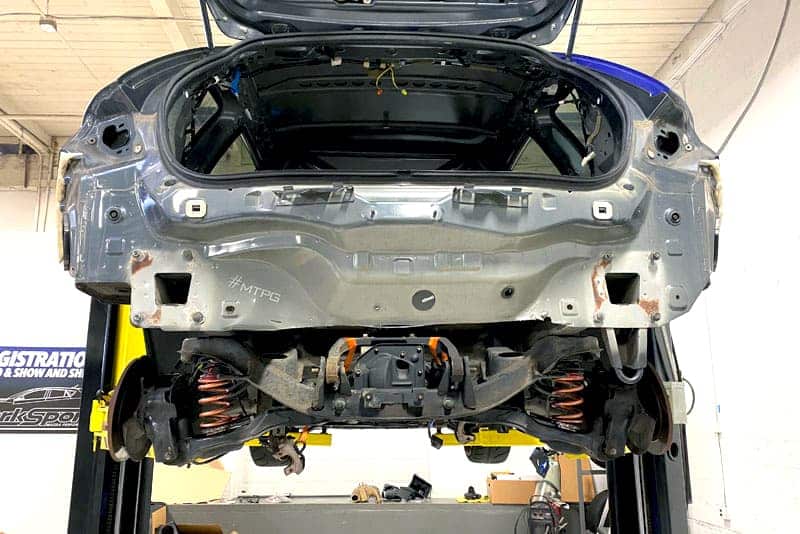
With both the MS3 and CX7 rear subframes out and sitting side-by-side, we took the opportunity to compare them. Checking the most important things first, we looked at the mounting points for the subframe to chassis. These all checked out visually and again after measuring to be the same…but this is where the similarities ended.
Comparison of the Mazdaspeed and CX-7 Rear Subframe Side by Side
The trailing arm/hub assembly is very different between the two models. The CX7 appears to be much heavier duty and more complex. Doing some research, we found that the CX7 uses a different style of parking brake. The parking brake is actually a drum brake inside the rotor hat of the disc. Either way, the CX7 suspension looks heavy…which is not ideal for Racecar. The width also appears to be wider by a few inches.
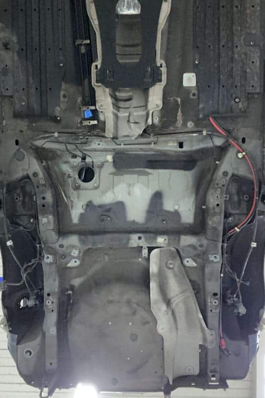
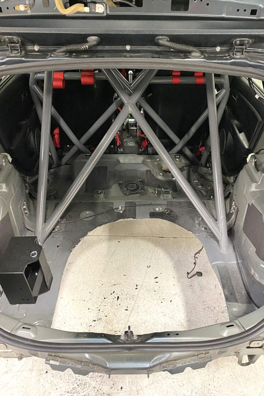
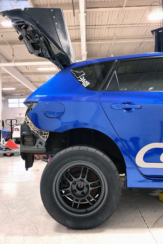
The last noticeable difference is the addition of a rear differential – which is the whole goal of the project – so that is a good thing! That said, the OEM spare tire location in the MS3 will interfere with the fitment of the differential.
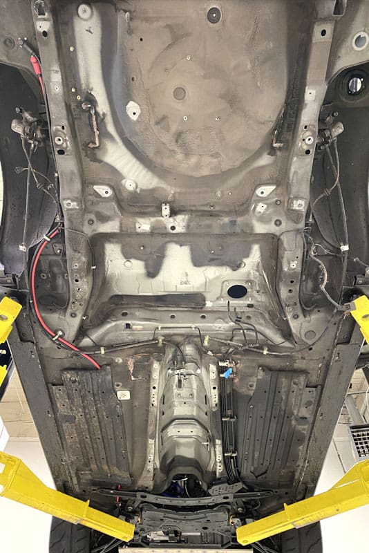
Not an issue for Racecar and my Sawzall! I cut the entire spare tire tub out since my new fuel cell will be going there.
Removed Mazdaspeed Spare Tire Compartment
We are ready to mock up the complete CX7 rear suspension with the spare tire tub removed. Knowing that the mounting points are the same, we installed the entire CX7 system to see how it fit.
The six mounting points lined up perfectly, confirming our initial measurements – it’s almost as if it was meant to be! Next, we tried to get the trailing arm forward mounting points bolted in but fought them, eventually giving up. We are confident the springs were fighting us, and the trailing arms would have bolted in had we removed the springs.
Installing the CX-7 Rear Subframe to the Mazdaspeed
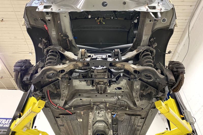
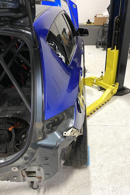
Moving on, we wanted to see how the track width looked before spending any more time on the trailing arms.
The Track Width of the New Rear Subframe
As we suspected, the setup was too wide – unless you want wider – which I did not want for a high-speed straight-line drag racer.
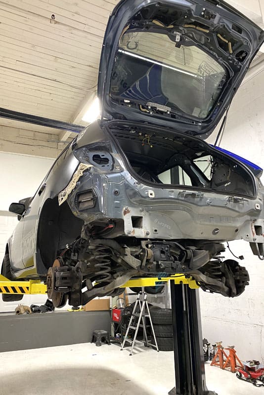
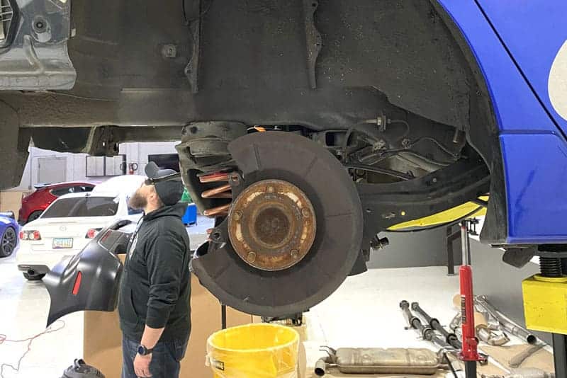
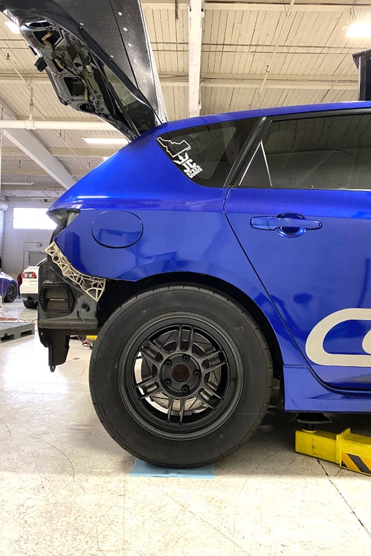
Ride Height with the Mazda CX-7 Subframe on Mazdaspeed
From the side view, the wheel’s centerline looks good, and the meaty 255/50R16 looks badass, but the CX7 springs obviously do not play nice. The monster truck ride height won’t work.
We planned a “hybrid” of CX7 and MS3 suspension parts, as advised by a friend, @junkiebuilt, that did a GEN1 AWD swap using a Honda drivetrain. We will use the CX7 subframe only and the MS3 trailing arm/bearing hub and control arms.
This combo was the ticket! The Mazdaspeed 3 control arms bolted into the CX7 subframe without issue, allowing me to retain my CorkSport Camber Arms and CorkSport Toe Arms, as well as the lower OEM control arm. Along with that, I get to keep the Mazdaspeed 3 trailing arm, which is not nearly as heavy or complex.
This setup also retains the OEM parking brake, my Mazda 5 rotor, and my MS3 calipers. Ultimately this is looking like a very straightforward swap with no fabrication. Don’t mind @farvaspeed6 looking at, um, something.
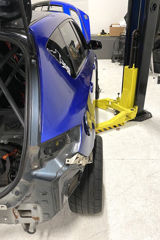
With the hybrid CX7/MS3 setup on the car, we wanted to see how things were lining up. The meats went back on!
After the hybrid swap track widthMazdaspeed AWD Swap Hybrid Ride Height
Ah, much better this time. The wider stance is gone, and the wheel tire looks right at home. Surprisingly the tire tucks under the fender with just a tad amount of rubbing.
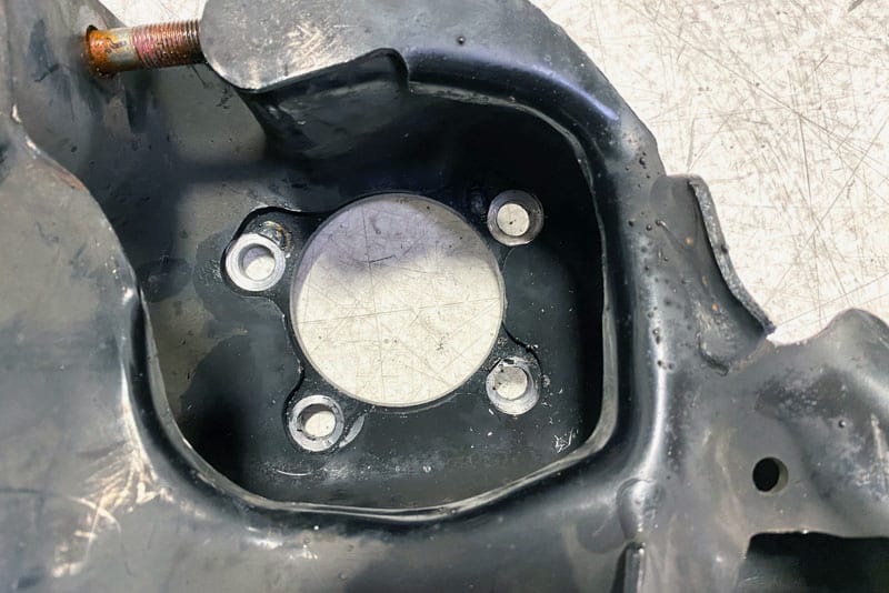
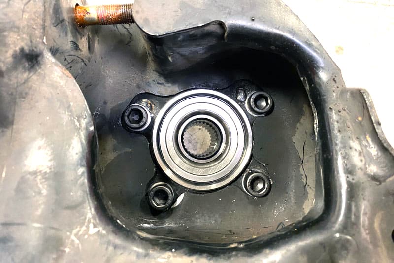
With the day of excitement winding down, I wanted to check on the last thing to see if this truly was a direct bolt-on swap. Unfortunately, the OEM MS3 rear wheel bearing is not the same as the CX7 wheel bearing. Being FWD, the MS3 wheel bearing does not have splines for an axle…duh. So I have to use CX7 wheel bearings on the MS3 trailing arm/hub assembly.
This is where my luck ended.
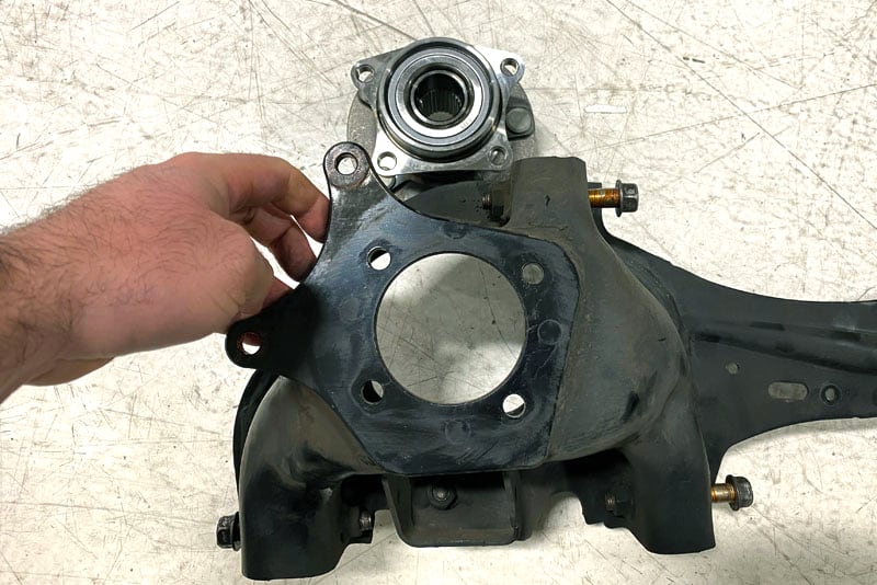
With the MS3 wheel bearing removed and the CX7 wheel bearing set next to the trailing arms…things look good. But they are ever so slightly different.
The CX7 wheel bearing has a slightly larger bore size, and the bolt pattern is somewhat different. I will never understand why Mazda went through the effort to make these so close but not the same. Either way, this was not a job a hand drill and grinder could fix. This needed proper measurements and machining.
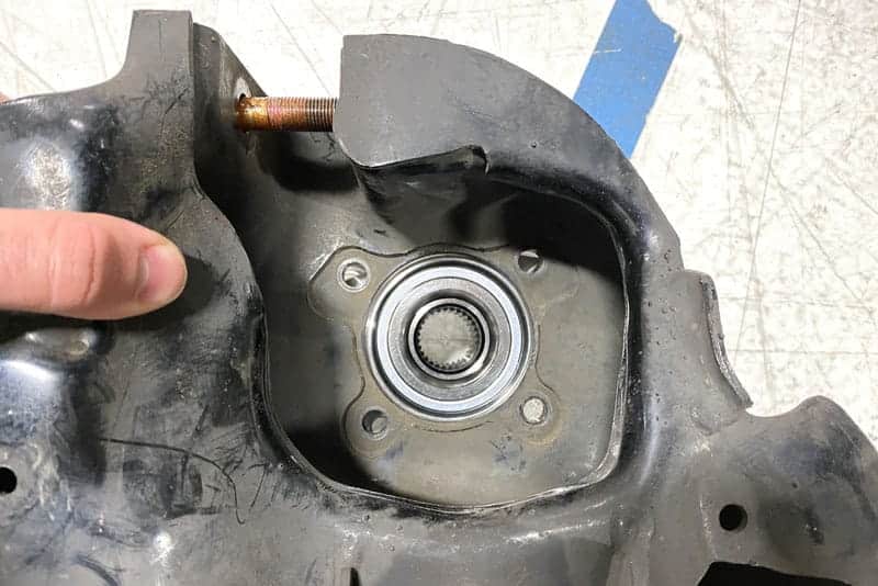
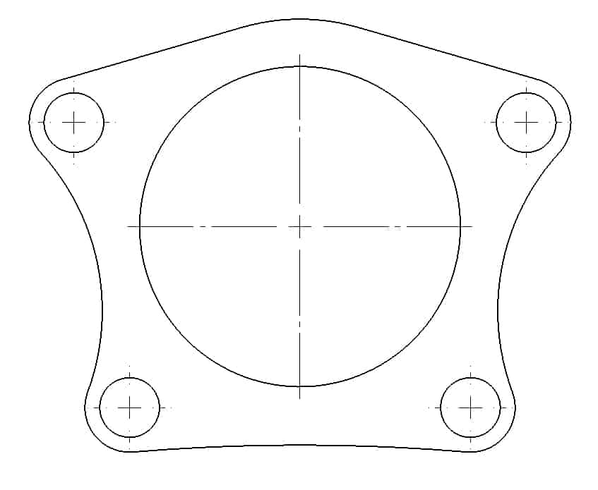
I reverse-engineered the CX7 bolt pattern and hub bore. 3DP printed that to verify then off to the machine shop to get the one-off work done.
The existing bolt holes were welded closed, the ground flat, and the new holes were drilled following my measurements. The hub bore was also enlarged to match the CX7 wheel bearing.
With that one and only fab job complete, we had actually finished the CX7 to MS3 rear swap.
Minus the machining for the wheel bearings, the rear subframe, and the suspension swap was actually very easy and straightforward. This is great news because it could have been the death (or very expensive aspect) of the swap. Ultimately this part of the swap being so easy makes it a much more viable project for the average enthusiast.
Alright, that wraps up the rear subframe swap, a huge milestone for the build. There are plenty more milestones to overcome and those are coming up in this multi-part blog series!
I hope you are enjoying this series about the AWD Swap Mazdaspeed 3, stay tuned for more blogs to come!
Part 2 of the Mazdaspeed3 AWD Swap blogs, we are going to get a baseline weight, show you some of the parts going into the car and finally tease you with cantilever suspension. Have a seat and grab a drink!
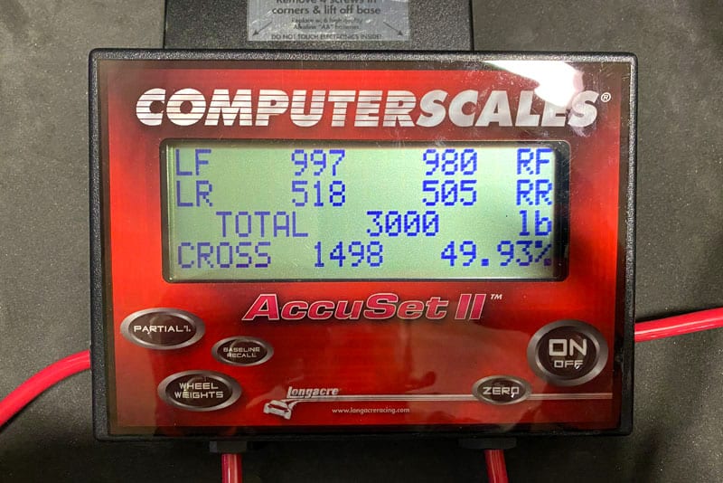
Before I started the AWD swap on my half-mile drag-racing Mazdaspeed 3 I wanted to get a baseline weight and weight distribution. Without a driver, my 2009 Mazdaspeed 3 weighed in at 3000 pounds on the money with just under 2000 pounds on the front wheels and just over 1000 pounds on the rear axle.
Corner weights are actually pretty damn good, but this is without my weight in the car. Adding me to the equation would throw that off a good amount. Either we have a baseline that we can compare to later once the car is back to 100% with AWD.
Now this may not be a perfect back-to-back test but it’s something…which is better than nothing. At the time of weigh-in, the Speed3 has an 8-point cage, composite driver seat and basic reclining aftermarket passenger seat, harnesses for both, stripped interior for everything behind the driver.
The components that are changing for the AWD swap:
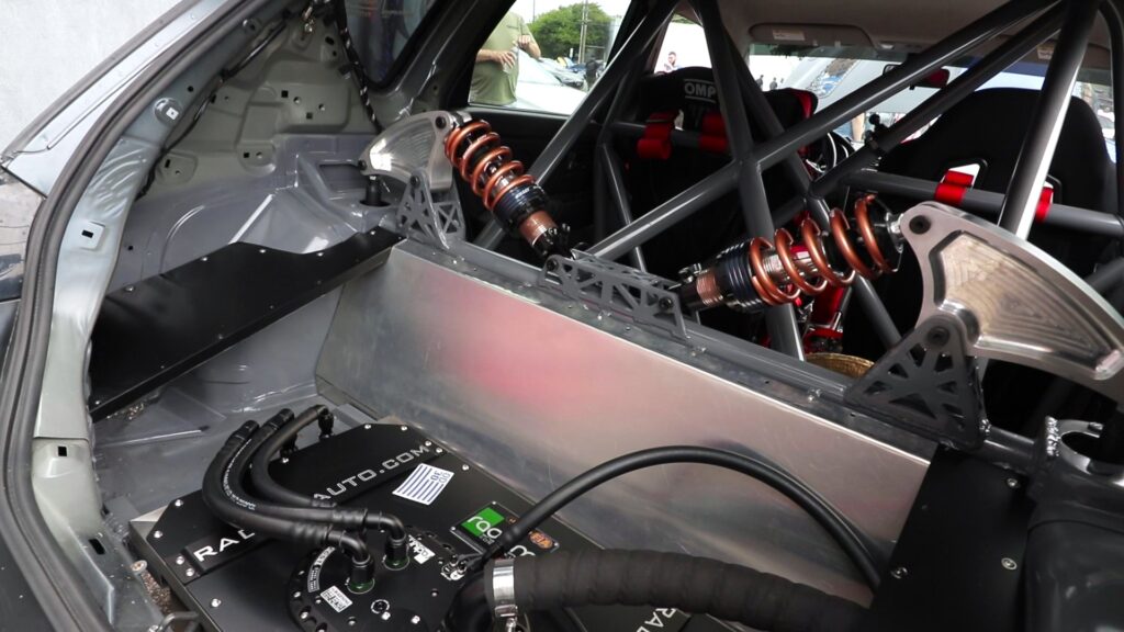
Firewall Structure to separate the Radium Fuel Cell from the driver compartment
Alright so let’s talk about some of these components that are changing. Firstly is the fuel system. Currently, I am running a dual fuel system featuring the CorkSport Fender Fuel Cell with E98 in it feeding the port injection system and the stock fuel tank with an E48 blend in it.
While this kit has taken me to 650+whp with the CorkSport CST6 Turbo and nearly 900 WHP with a larger turbo and fuel pump…it’s time to really focus the build to a more dedicated racing fuel system.
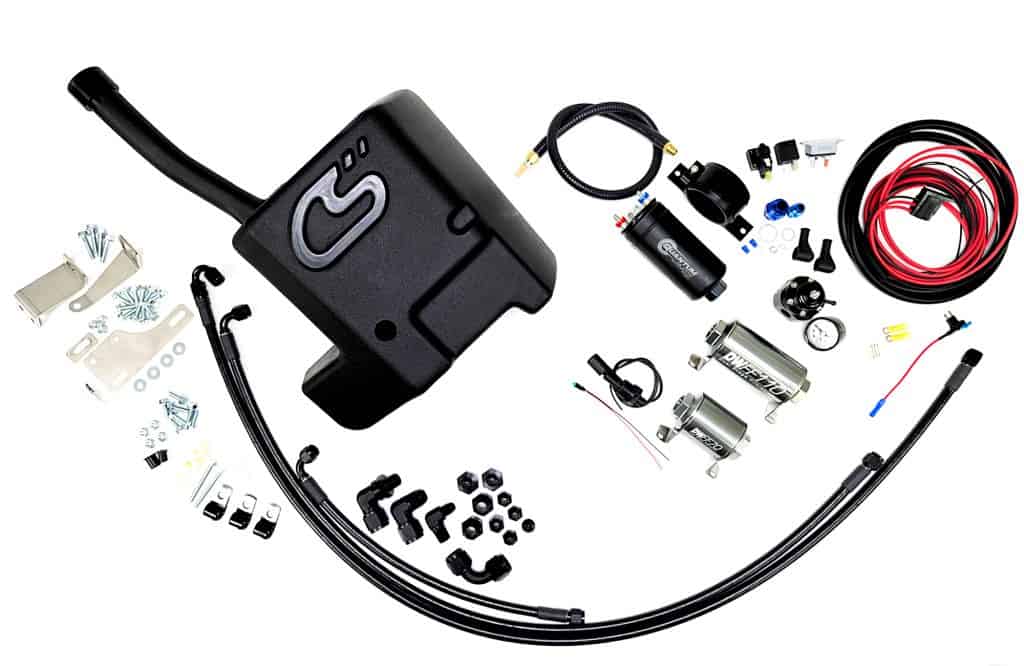
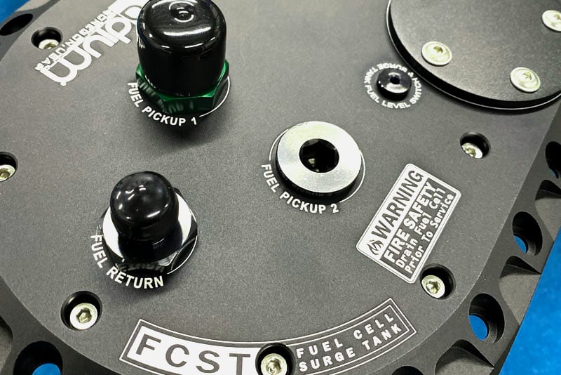
Enter the Radium “FCST” System; this is a full standalone fuel system that is FIA-certified and incorporates the 10-gallon fuel cell, an internal surge tank, and a fuel level sensor.
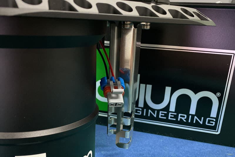
For my setup, I will be using a single 525LPH “in-tank” pump inside the fuel cell feeding the surge tank which then feeds to external pumps. This 525LPH fuel pump is mounted to the stainless steel bracket you see below inside the fuel cell.
Then the external pumps are a Quantum 044 style pump feeding the direct injection OEM fuel system and a MagnaFuel 525 gear-driven pump feeding the port injection fuel system.
So why the big change? Well, there are a few reasons really:
With the AWD swap, I couldn’t retain the OEM fuel tank due to the mid-driveshaft so I had to find a new solution. There is some Volvo OEM fuel tank that works with some basic modifications, but this is a racecar. I did not want to retain the same limitations as OEM.
With the power I am pushing and plan to push in the future, I need all the octane I can get so it made sense to use a single tank feeding both DI and PI fuel systems.
Typically, in drag racing, you specifically use a small (less than 3 gallon) fuel cell in the front of the car, much like the CS Fender Fuel Cell. However, my car still sees street use, at events, and may or may not always be a drag racing-only car so I wanted a fuel cell system that could do anything I wanted now and in the future.
Next up is the rear suspension…this is my favorite part…except for the actual AWD of course! With the rear suspension, I am taking a much more unique approach by using an inboard mounting cantilever coilover suspension. While this seems over complicated upfront, and it is, it will also provide me with a lot of flexibility and control later when using and tuning the suspension.
But what’s wrong with the OEM suspension design?
Nothing is “wrong”, it’s just not ideal. The lower control arm that supports the coil spring is very heavy, the OEM damper mount can’t be used due to the driveshaft so I will need to create a new mount elsewhere with cantilever or OEM style suspension and lastly, I want double adjustable (rebound and compression) dampers which would be more difficult and expensive to source that will work in the OEM style arrangement.
All of those factors lead me to the path of developing my own suspension setup.
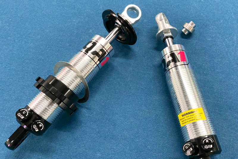
Doing some research I found QA1 dampers have great reviews, are very cost-effective, come in many different sizes/lengths, and have double adjustable options. They seem very fitting for my goals.
The double adjustable control is important for any type of competitive racing, but with drag racing, I had a specific need. When the car is launched from a standstill, there is an extreme amount of weight transfer happening that needs to be allowed to “transfer” to the rear but then needs to be controlled and maintained in that position.
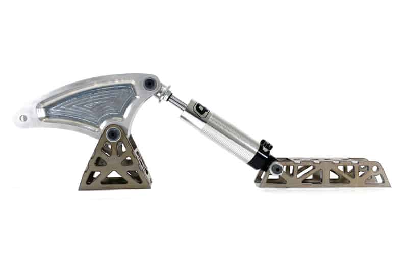
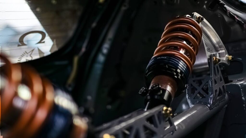
Lastly, what is this cantilever suspension and what does it look like? Here’s a teaser of my design.
While I am planning to dig into the design around this in more details, that will have to wait til the next blog in this series. In a nutshell, the outboard suspension that the wheel and tire is connected to pushes a “push-rod” to a larger rocker arm (cantilever) that then pushes a coilover damper and spring setup. Other than the rod itself, this entire system is inside the car between the rear damper towers.
I hope you are enjoying this series about the AWD Swap Mazdaspeed3, stay tuned for more blogs to come!
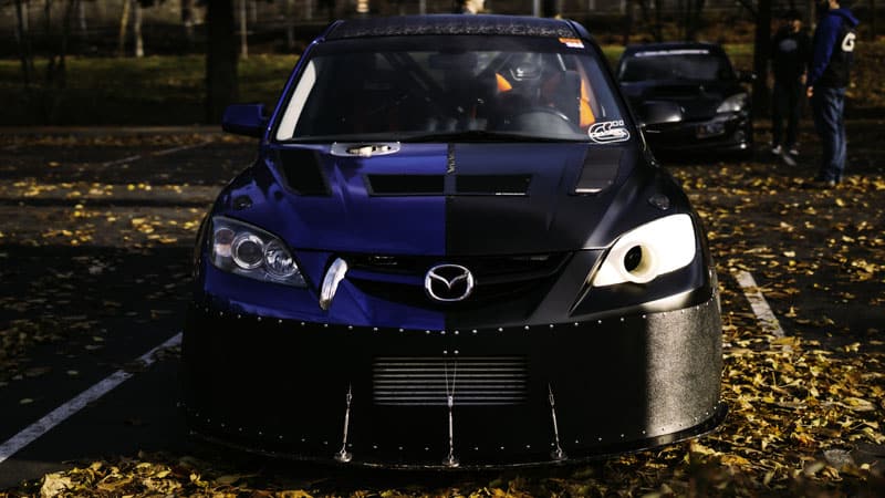
Have you ever felt like you try and try and try, but just can’t get the traction to make forward progress on your Mazdaspeed 3 car build? Ya, it happens to the best of us and the 2022 season was my time…both in literal traction and life.
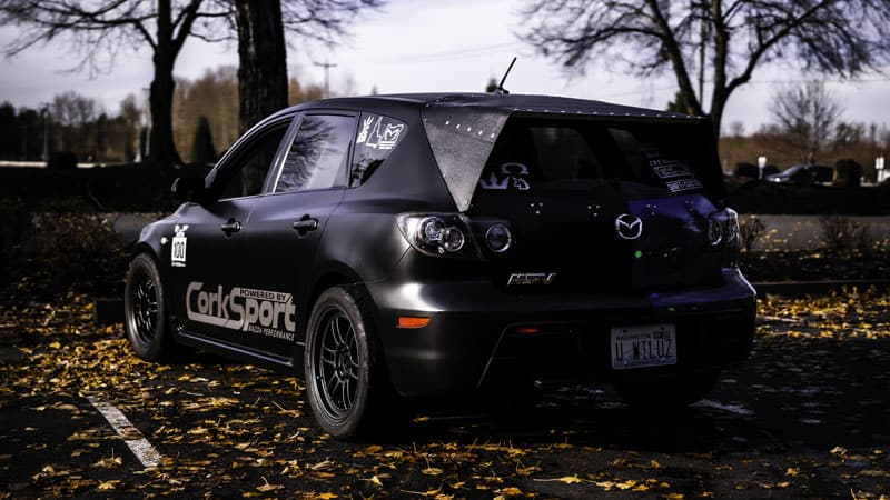
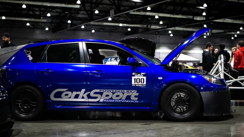
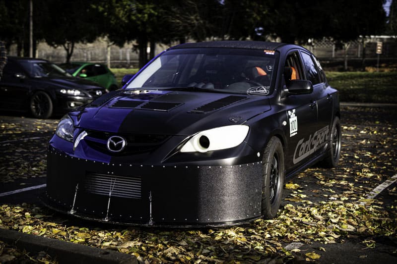
If you haven’t seen my build yet, the @halfmilespeed3, go check it out. It’s an awesome combo of DIY, Teamwork, Innovations, and CorkSport goodies you all love.
Back to this traction conundrum. Racing an 800+hp FWD Mazdaspeed 3 on small airport airstrips with no prep and plenty of dust has proven to be challenging. There have been many successes and many challenges, but ultimately it comes down to those two tiny patches of rubber that meet the road.
LITERALLY NO TRACTION
Yes, Motec helped substantially with traction control and Justin’s ramp-up in power delivery also helps, but really…I just didn’t have any damn traction. Sticky tires with meaty sidewalls also help, but again traction was such an issue! There had to be a better way!
Wheel & Tire Setup:
Front: Toyo TQ 255/50 on 16×8+38
Rear: Toyo R888R 255/40 on 17×9+45
And there was and I had been talking about the idea for a year or so already. Then life happened.
As you can see with the racecar; I like to go fast. I carried that enthusiasm into my love of mountain biking one day in June 2022 and well…I got a lesson in physics let me tell you.
Five broken ribs, a double punctured lung, level 3 AC separation, and a fractured collar bone and scapula. Resulting in weeks of hospital stays and three surgeries; then months of recovery and physical therapy. Let’s just say the 2022 season did not go as planned.
But it did get me focused on solving my traction problems…
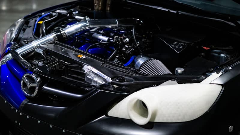
Mazdaspeed 3 with CorkSport Mazda Performance Parts Back (AKA HalfMileSpeed3)
The Goal…Mazdaspeed 3 AWD Swap
So I decided it was time to stop talking about it and actually take action (well as soon as I physically could that is). I made a plan and figured out the details and order of operations to finally get my traction back.
While I am not the first to do a Mazdaspeed AWD swap. I did have a goal to make my build unique in the sense that the AWD swap is catered to racing performance. Meaning the strength of custom parts and the rear suspension design and the new fuel system are capable of handling the 4-digit horsepower goal I have and the abuse of racing.
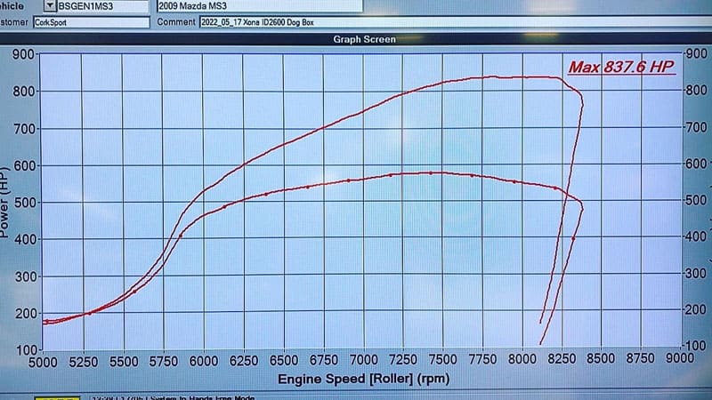
Talking horsepower…what does the car make right now?
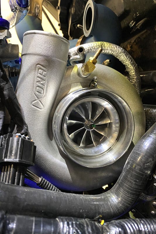
This is at a modest 40-41psi using a Xona Rotor 9569s with the X3C compressor housing and 1.03A/R turbine housing. Later Justin @freektune and I turned it up a bit more to see how close we can get to the 600wtq threshold and hold it. Clipping off an 881whp run…damn! This was supported by the many CorkSport Mazda performance parts you can get for your Mazdaspeed as well. From engine mounts to manifolds, anything that isn’t a one-off custom is CS.
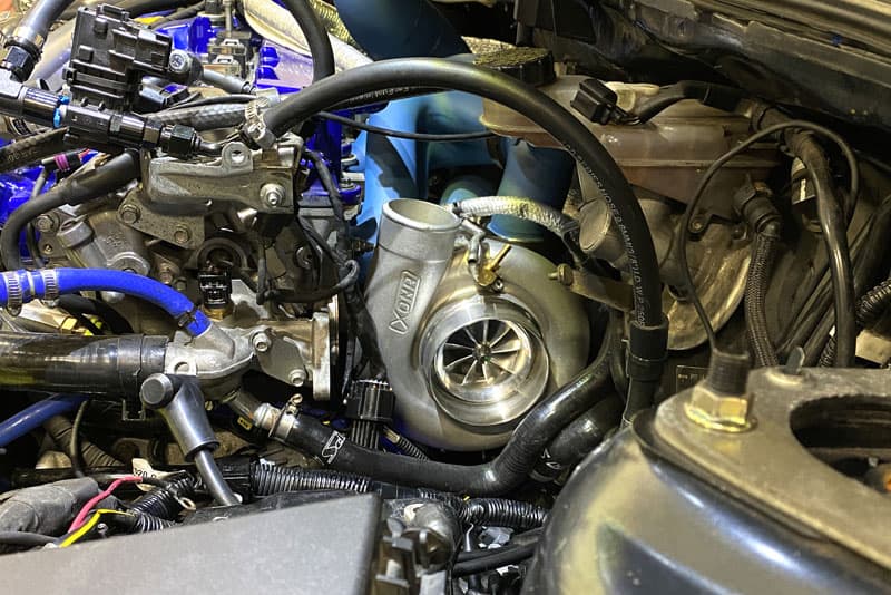
Anyways…I have since updated the compressor wheel to a 99 lb/min design compared to the above 95 lb/min design and a larger compressor housing which is more efficient. This setup has not been dyno tested yet, but talking to the engineers at Xona…2023 is going to be spicy!
Close up because who doesn’t like billet turbo shots!?
Dare I say this is the largest turbo in the stock location ever on a Mazdaspeed? Go ahead…prove me wrong. To compare, this competes with a Precision 6870.
The Start of the Mazdaspeed 3 AWD Swap
Anyways, this is the introduction to my Mazdaspeed 3 AWD swap here at CorkSport HQ. I actually started the swap in October 2022 and have been making big steps each month. We are going to be sharing blog updates rapidly as I wrap up the swap over the next couple of months.
There will be much more technical info and images coming up so grab a drink and enjoy!
You can also find updates on my IG @halfmilespeed3, the CorkSport 7th Gear Membership, and on mazdaspeeds.org.