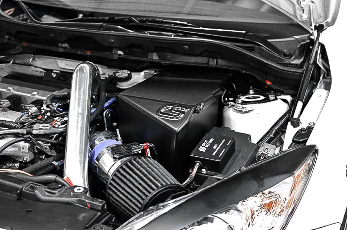
We love the clean and simple look of the CorkSport full-size battery box and we know you do also. Our goal was to bring that same level of awesomeness to all the big power guys and gals running 4” intakes and 51R batteries in your Mazdaspeed.
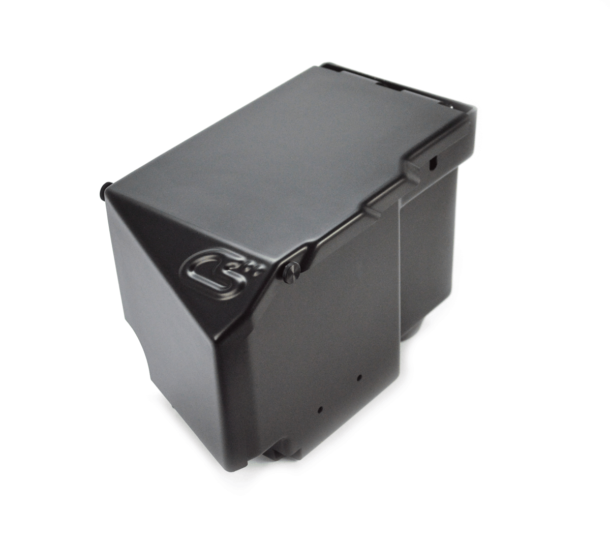
We knew we couldn’t compromise on the fit and finish you’ve grown to love, and this new battery box doesn’t disappoint.
The greatest challenge came in the form of locating the ECU inside the box; as that is the whole point of the CorkSport battery boxes. With a bit of massaging and adjusting, we innovated a sleek solution for the ECU placement without compromising the style and fitment of the battery box.
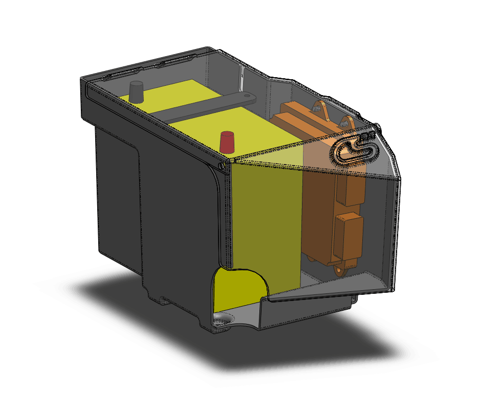
In the original CorkSport Mazdaspeed battery box, the ECU was located on the front panel. This packaged well with the full-size battery and made access easy, but in order to increase the clearance for a 4” intake system in your Mazadaspeed, we had to reduce the width of the battery box as much as possible. This required us to rethink the location of the ECU and the overall design of the battery box to accommodate it. Check out the computer-drafted model below.
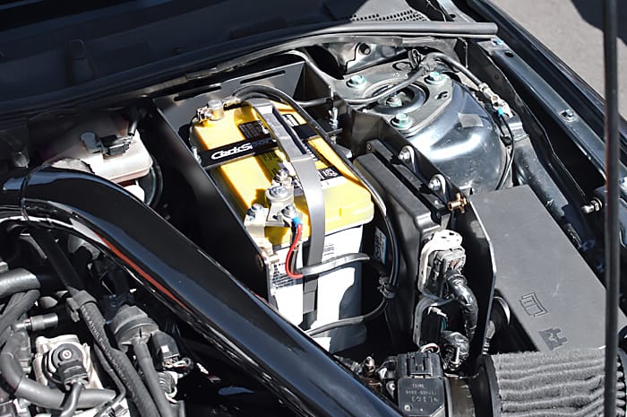
Moving the ECU to the side provided ample clearance for a 4” intake system and retained the standard battery location. The front of the battery box had to be extended out a bit, but this also gave us a chance to keep the wiring harness inside the box to maintain the high-level fit and finish. To finish off the installation, the battery is retained with M6 studs fastened into the battery box and a 0.120” anodized aluminum bracket.
If you’re looking to downsize your battery, upsize your intake system, or are just plain tired of looking at all those unsightly wires then let the CorkSport 51R ECU Relocation Battery Box be the answer to your goal.
Oh wait, it’s not December. It sure can feel like it sometimes when you are getting more and more parts in the mail. Am I right?
So let’s get down to business here.
This will be the one and only time you hear me say that your side chick needs to be MORE FLAPPY! If you want to protect her skirts, and booty, then making her flappy is a definite must.
CorkSport is proud to announce that we are bringing back our 2010-2013 Mazda 3/MS3 Mud Flaps by popular demand. Ask and you shall receive!
Made from 80 durometer urethane, these 1/8 Inch thick flaps will protect all of your painted surfaces, and result in a cleaner rear hatch.
How does this really affect you? Well, have you ever tried wiping without toilet paper? I can tell you that it can be a tad bit messy. Go ahead and skip the dirty booty by adding these to your Mazda 3/Mazdaspeed 3. 2010-2013 Mazda 3 & MS3 Mud Flaps (Set of 4)
A few extra tidbits about the mud flaps:
Durable 80A 1/8inch thick polyurethane.
CorkSport logo laser etched into the mud flap.
2-year limited warranty.
These are a must-have if you are trying to increase style while still being functional. I can tell you that these definitely help to keep the rear hatch cleaner makes it easier to keep the entire car cleaner for longer periods of time.
You’ve probably heard the phrase “built block” lately on social media or at your local car meet, but you might be wondering what that actually means. In fact, you’ve probably heard it enough times that you don’t even notice it. For you newbies, it’s when the engine internals are replaced with performance parts. Whether you do or don’t understand what a built block is, I thought I would share my knowledge and experience through the engine building process for my 2009 Mazdaspeed 3.
The incident
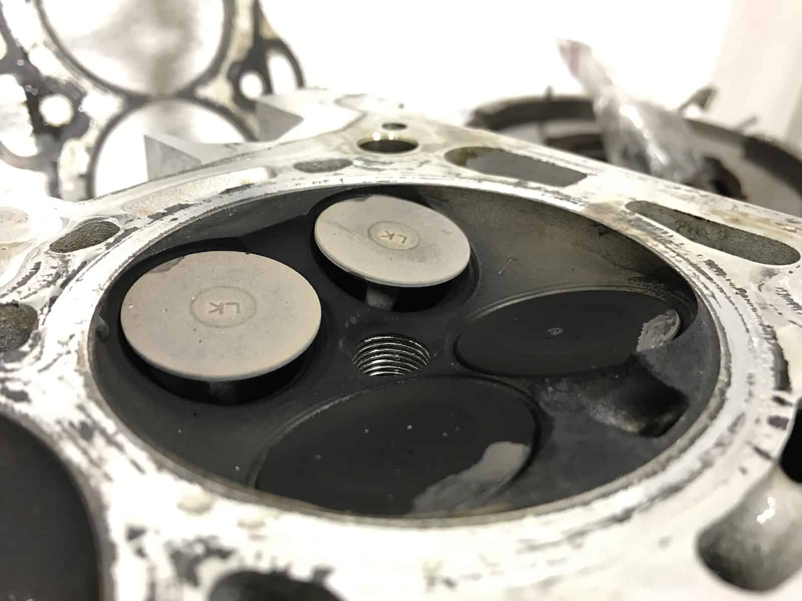
The moment we all dread (or maybe even look forward to?) finally happened … zoom zoom BOOM (ZZB). I was merging onto the highway, within the speed limit, when the engine went silent and my dashboard became a Christmas tree of lights. I tried to start it … nothing. Well, shit.
I called the tow truck and brought my Mazdaspeed back to CorkSport HQ. A compression test gave me the quick, sad story. It was 0 0 0 0 across the board. Obviously, something gave out. That something turned out to be the friction washers on the crankshaft.
I now pronounce you piston and valve. You may kiss the valve.
The diagnosis
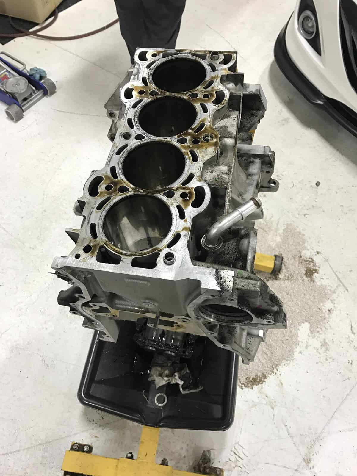
The engine slipped timing and bent all of the valves. Luckily, I didn’t vent the engine block in the process, so that could be reused. After all this, I didn’t trust the engine. So it was time to get built!
The bare block from my Mazdaspeed.
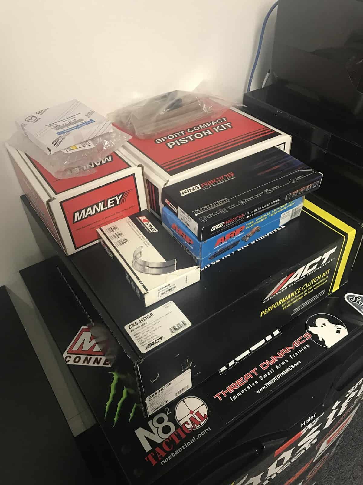
I pulled the engine and transmission from the vehicle and stripped them down to the bare components so the machine shop could do their magic. But, before we could let them start, I had to get some parts ordered for the machine shop to consider in the build tolerance. Just look at that stack of money … I mean parts.
The engine build parts
Forged internals for the Mazdaspeed.
The bare engine block, a new used cylinder head, ACT 6-Puck clutch, and forged internals were sent to M & B Cylinder Heads for some much-needed love. The block was bored and cross-hatched to match up with the pistons, the main bearing journals were line honed where needed, and the deck surface was cut down just a hair to provide a new surface that’s true and flat. Since I wasn’t going for just a bare bones build, I opted to have some added processes done to help with reliability and performance.
I planned to run without the balance shaft, commonly called a BSD (balance shaft delete), to increase the oil capacity of the oil pan. This would remove some rotating mass to help the engine rev more freely. However, this does come with some compromises, mainly in severe NVH (noise, vibration, harshness) the driver experiences. For this reason, I had the rotating assembly (crankshaft, connecting rods, pistons, clutch assembly, and crank pulley) balanced to further reduce vibrations.
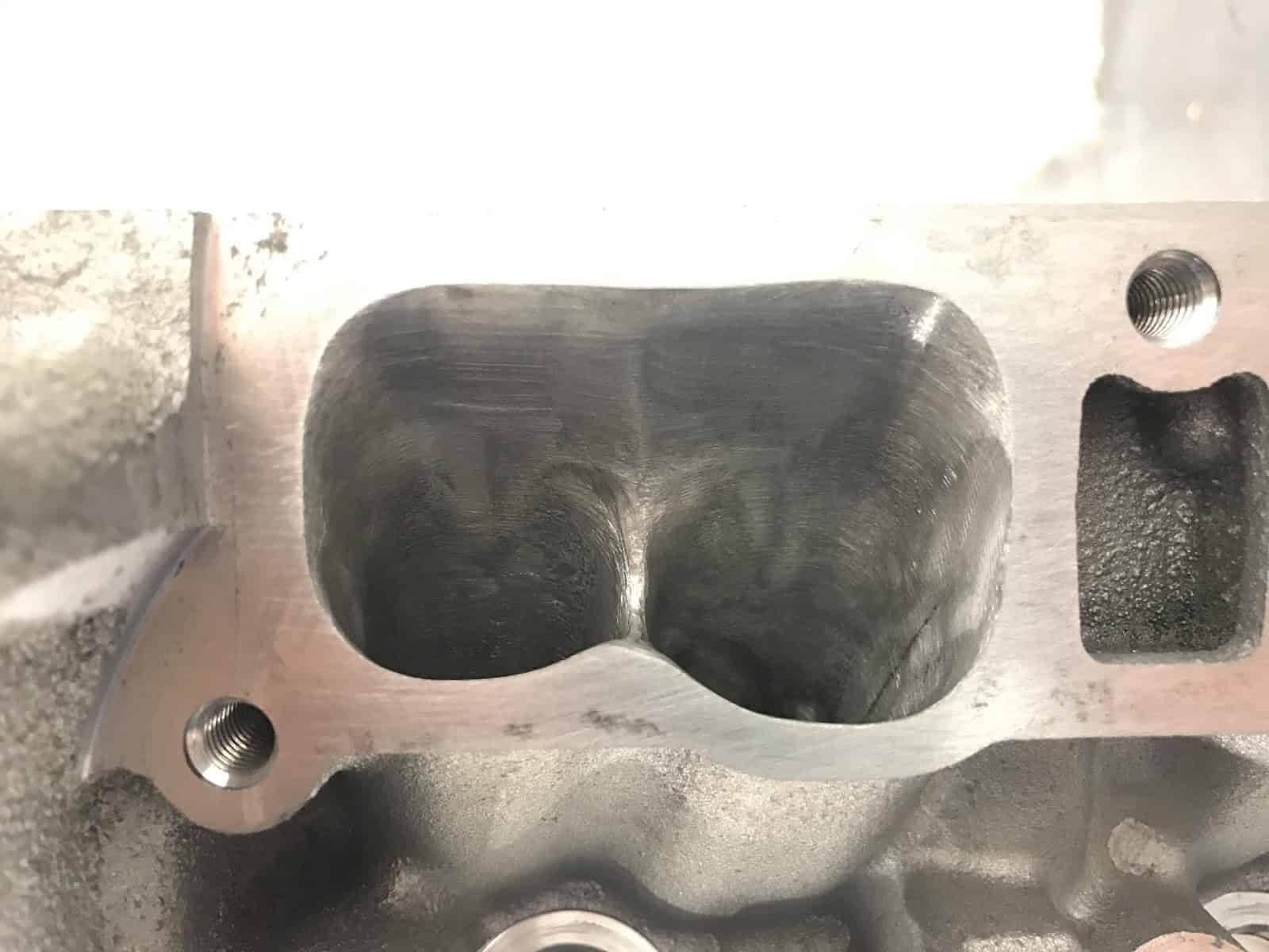
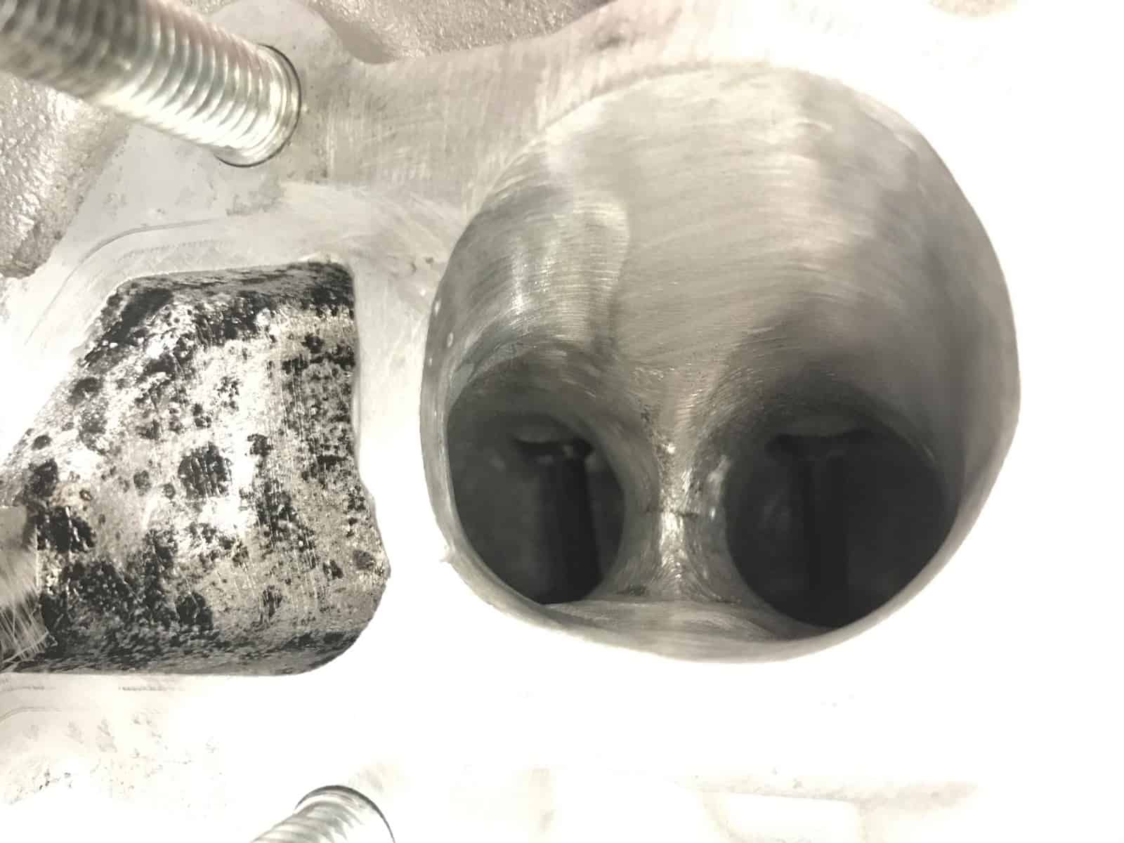
My build goal was at least 450 whp to further benefit the effect of the CorkSport Mazdaspeed camshafts, so I had the cylinder head ported to improve flow. The intake runners were opened up and cut to a single runner setup along with the exhaust ports. Both intake and exhaust had most of the work performed on the “bowl” area of the runners — the area just above the valve seat. To top it off, the combustion chamber was touched up to remove any sharp points to help reduce hot spots that may cause detonation.
Check out the cylinder head porting:
Here’s the single runner.
And here’s the exhaust runner.
The engine build operation
After what felt like an eternity, we got all the completed parts back from M & B and were ready to begin the assembly process. This is when I really stepped back and let Vincent take the lead. He’s the master when it comes to engine blueprinting and assembly.
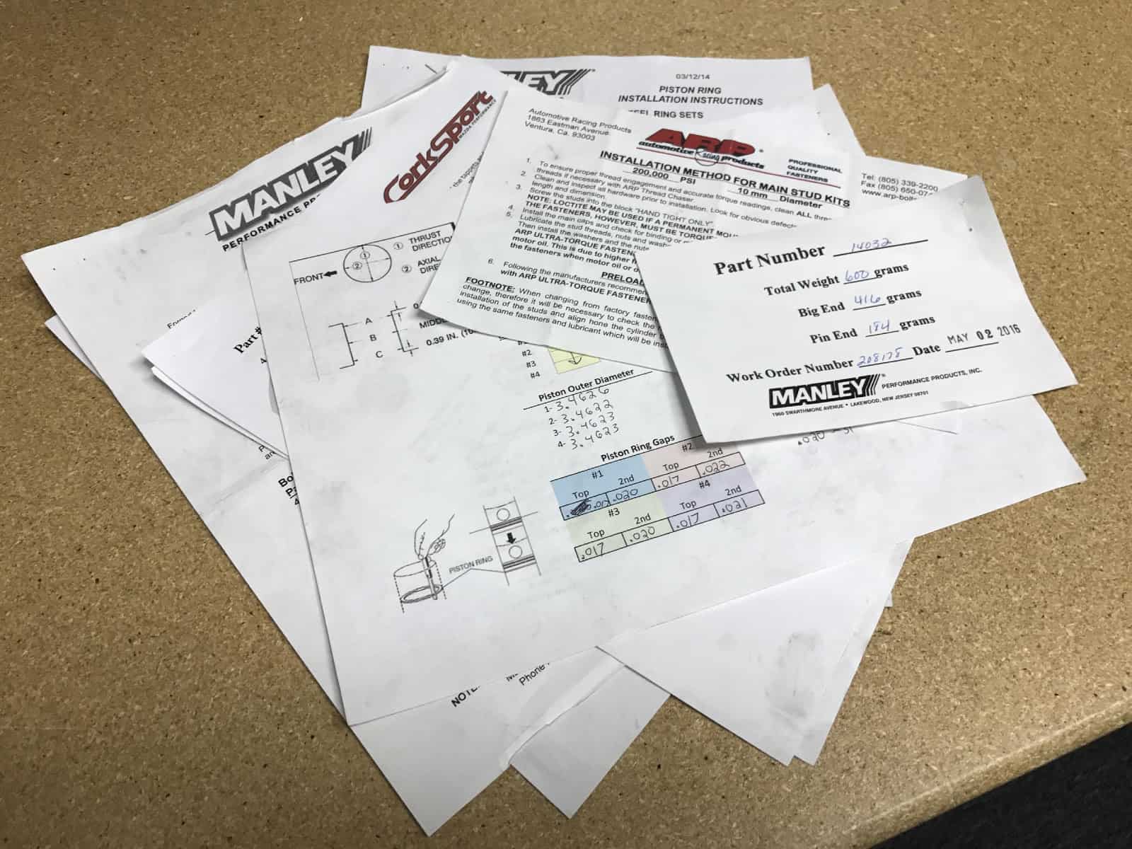
The blueprinting process is arguably the most critical and time-consuming process of the engine build process. Each cylinder diameter is measured at three different vertical locations to determine cylinder taper, then measured again 90 degrees from the previous locations to determine cylinder roundness. The piston outer diameter is measured as well and verified for the cylinder it was matched to at the machine shop. Once the block and pistons are confirmed, then the finer details are set in motion with the piston ring gaps, the main bearing and connecting rod bearing crush, and setting the main and head studs. I’m just skimming the surface here. Please note that all of this is measured down to the tens-of-thousandths of an inch. That’s 0.0001” for clarity. This really is a precise art.
Precision means paperwork. Here are the blueprint papers for the Mazdaspeed engine build.
With the short block assembled, it’s time to focus on the cylinder head. The cylinder head almost seems easy after the short block assembly. The cylinder head comes assembled with the seals, valves, and springs from the machine shop. What’s left to Vincent is the tappet and camshaft installation. The tappets are non-adjustable solid tappets and each has a specific and precise thickness. Once the camshafts are installed, the gap between the camshaft base circle and the tappet is measured and adjusted until the correct gap is achieved. Then the complete the cylinder head can be installed on the short block and the head tightening sequence performed.
I hope you enjoyed this tale as much as I enjoyed writing it. This not the end of my build, so hang tight for the rest of the engine and vehicle in a later post. We’d love to hear about your build, whether it’s a few bolt-on parts or a crazy built engine and car. Comment below and tell us about it!
You may be surprised to hear that there is yet another Rear Motor Mount available for the Mazdaspeed 3 platform in a market with more than a handful of options; however, this one is different. This RMM takes the idea box and kicks it to side as it makes a great leap towards style, performance and refinement. Ladies and Gentlemen, this is the new CorkSport Stage 2 Rear Motor Mount.
Mazdaspeed 3 Stage II mount
If you are even remotely familiar with the OE style (and many aftermarket options) RMM then you can clearly see that the CorkSport Stage 2 RMM is drastically different. Now let me explain why this is a good thing.
We all understand that the engine mounts isolate the engine from the chassis in an attempt to reduce and/or eliminate undesirable vibrations and noise experienced by the driver. That’s great and all, but what is really important is how the isolation is executed, specifically by the RMM. First, some background information.
There are three motor mounts working together to suspend the engine so let’s talk about the other two real quick. The transmission and passenger side motor mounts reside on the furthest ends of the assembled transmission and engine, respectively. These do most of the work supporting the engine given their positions, but a side effect of that is the aggressive rotational force they allow the engine to exert due to their transverse setup. This is where the rear motor mount comes in by managing the rotational force from the engine when applying power to the axles/tires.
Let’s take a look at the diagram below:
In the diagram, we are looking at the OE RMM installed on the vehicle. This view is looking at the RMM from the right-hand side of the vehicle. The diagram also attempts to show the general location of the transmission mount which is approximately where the transverse pivot point of the engine lies.
The engine exerts the rotational force onto the RMM shown with the double-end red arrow. This can be further broken down into directional components as shown with the blue arrows. The forward force is unavoidable due to the design of the system in a whole, but the downward force can be reduced or even eliminated with a clever design such as relocating the damping material from the OE location to a location closer to the engine pivot point. Note the length of the blue arrows as it will be different in the following diagram.
There are two key aspects of the CorkSport Stage 2 RMM that contribute to its superior performance and low NVH (noise, vibration, & harshness). First is the rigid design of the mount that installs into the sub-frame. This nearly eliminates any up and down pivot capabilities at the sub-frame thus reducing the magnitude of the up/down motion the RMM will allow. This feature has been used by a couple of other manufacturers in the community because of is superiority. Second, and more importantly, is the location and orientation of the polyurethane bushings. The horizontal orientation of the bushing allows the bushings to function and support the load in the same direction the engine exerts force. This results in a more durable design with less NVH.
Now comes the big game changer…the location of the bushings is in a location never done before in the Mazdaspeed 3 platforms. Comparing the OE RMM pivot location vs the CorkSport pivot location you will see that the CorkSport design moves the pivot point of the RMM forward in the vehicle. This is important because of how it relates to the natural pivot location of the entire engine/transmission. Moving the RMM pivot location further forward reduces the amount of downward force applied to the RMM at the sub-frame, thus reducing the NVH without compromising performance. This is shown by the different lengths blue arrows in the diagram. This allowed us to use very stiff 95A durometer polyurethane without compromising driver and passenger comfort.
Anyways, enough with the technical stuff; check out this video comparing the OE RMM and CorkSport Stage 2 RMM in action.
If this hasn’t blown you away already then let Jason Atwell’s Beta test review set it in stone for you…
“Tested out the new CS RMM and I’ve gotta say; I was dead set on the gold RMM I was currently using. Once I got the CS one, I installed it right away. The fitment was spot on, I hopped in the car and took it for a drive and noticed an even more solid feel in the shifts. The vibes are about the same as the gold RMM so all in all I’d have to say it’s a fantastic product and would recommend it.” – Jason Atwell
The wait is over! It’s finally the time of year where we shed the car covers, finish our tunes and builds, and make any last modifications to get fully prepared for the 1,320-feet road course racing season. As you can imagine, all of us here at CorkSport now have an extra pep in our step with the weather improving and our goals becoming clear.
Built for speed
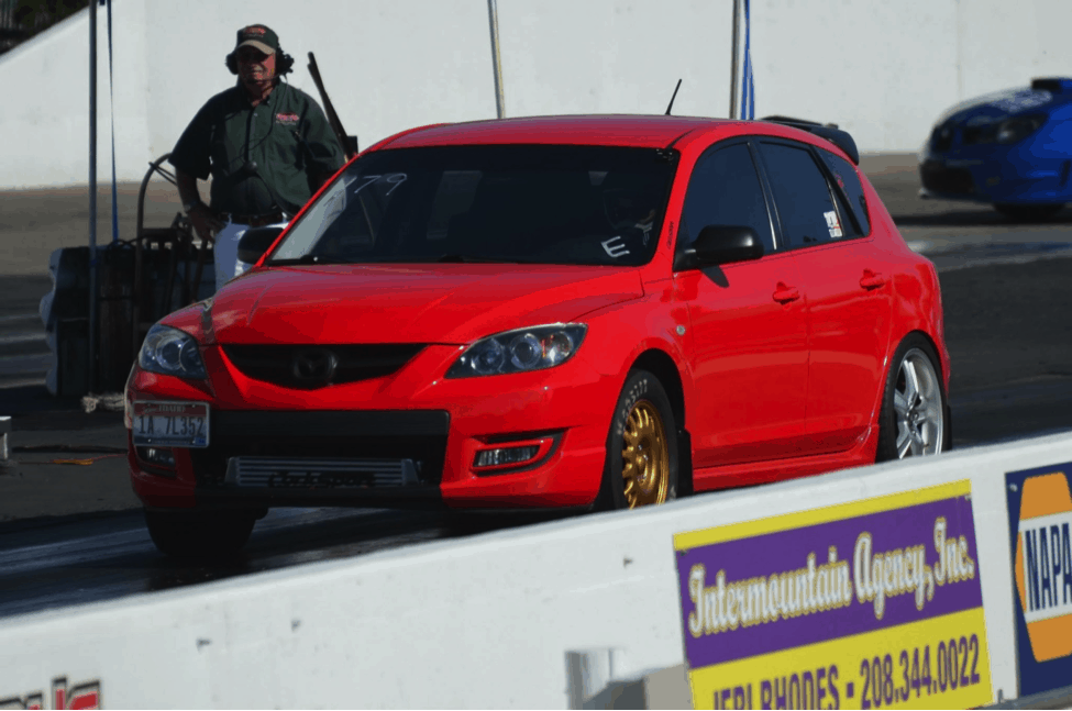
Because I live for racing, I’ve built my car specifically for the drag strip. I have a 2009 Mazdaspeed 3 decked out with:
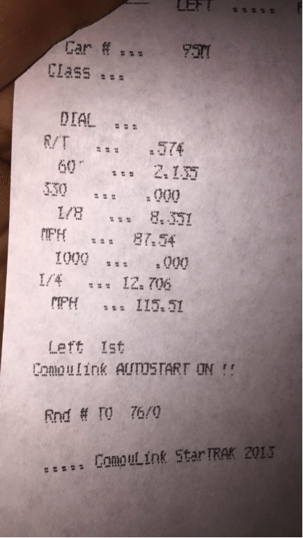
During last year’s season, I was able to lay down a pretty raw pass with my full bolt-ons, stock block, and CorkSport turbo. I was happy with a 12.7 elapsed time (ET) at 115 mph — a respectable number if you ask me! This year with my new built bottom end, I am hoping to have more midrange, spray more meth, and run faster. I have a personal goal of trapping 120 mph on the CorkSport turbo. Just imagine how sweet it would be to have a Mazdaspeed 3 trapping 120 mph in the 1,320 with almost no turbo lag!
Whether a racing victory is your goal, or you just want a modded-out dope-looking ride, we want to make sure you guys think about CorkSport when you are looking for parts. I’m proof that our turbo with full bolt-ons is capable of impressive speed. Whether you need suspension components, turbo components, or you just want to have a chat, you know where to find us!
Cheers,
Luke
2017 Race Season Is Here! February 6th, 2017Derrick Ambrose