Welcome to part 5 of the Mazdaspeed3 AWD Swap (sorry for the delay; things got really busy for a bit)! This blog covers the rear-end drivetrain and the huge modification that makes it all work.
There are a lot of images and explanations of those images so you can see and understand the differences between the Mazdaspeed 6 and CX7 rear drivetrain.
What is the Rear Differential
Jumping right into it, let’s identify what the rear differential is. The rear differential transfers power from the transfer case via a PTO/driveshaft, through the ring and pinion, out to the axles, and then to the wheels and tires.
However, as with many modern AWD systems in compact cars, there is a clutch mechanism between the PTO/driveshaft and the differential. This clutch mechanism controls the percentage of engine torque transferred to the rear tires.
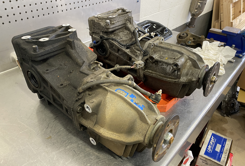
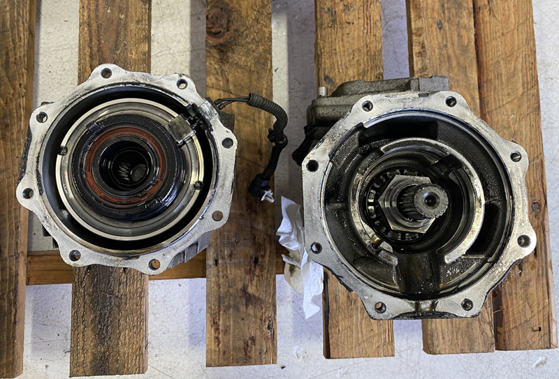
In the diagram below, we’ve identified the two major sections of the differential assembly. The line demonstrates the connection point between the two sections. The rear section is the gear housing, and the front is the clutch housing.

Now that you understand the differential assembly. Let’s identify the difference between Mazdaspeed 6 and CX7. There are two major differences.
Differences In Differential
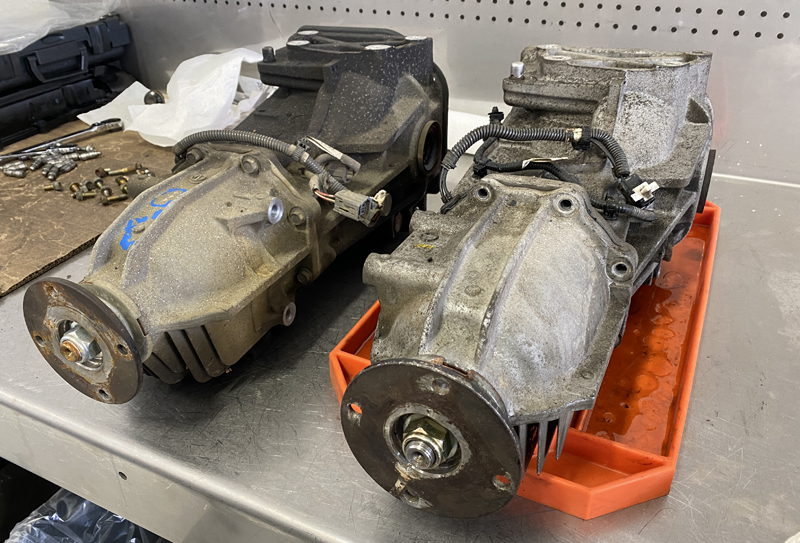
The first difference is the clutch housing mounting points for the front subframe mounting brackets. In the image below, you will see two mounting points with threaded holes on the right side of the differential, while the other differential does not have those mounting points.
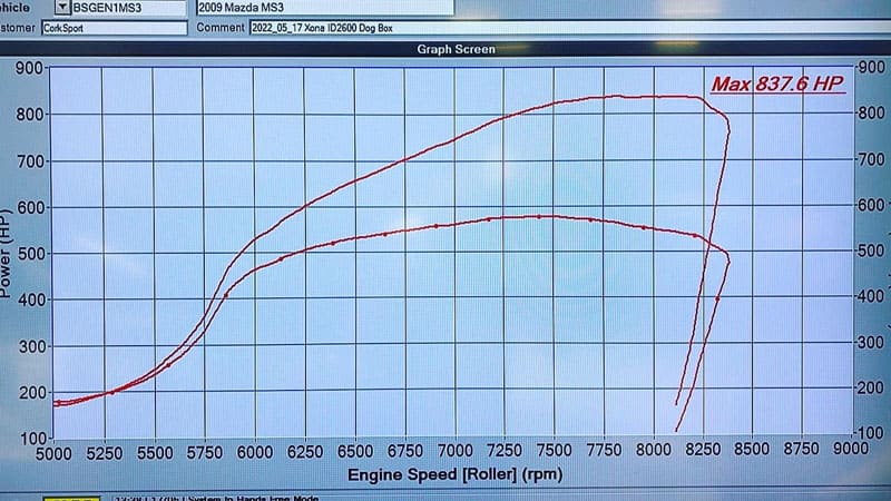
The CX7 differential is on the left, and the Speed 6 is on the right. The CX7 on the left)has TWO front mounting points whereas, the Speed 6 only has a ONE mount. While this may not be a big deal for a daily driver with modest power levels, it’s a huge advantage for a racecar with nearly 900whp.
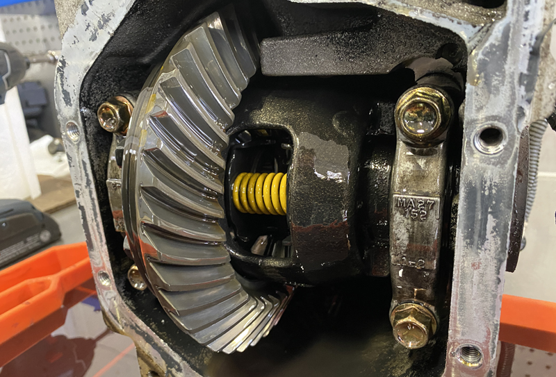
Moving to the inside of the gear housings, the CX7 uses an open differential setup, vs the Mazdaspeed 6, uses a Mazda proprietary LSD (limited slip differential). The LSD is more desirable because it will provide better power distribution to both rear tires vs the open differential.
Fun Fact: the Mazda-developed LSD uses “friction cone washers” sandwiched between the spider gears and differential carrier housing to create the limited slip effect. As load is applied through the spider gears, the increased load presses the spider gears against the friction washer, which makes this a very street-friendly and progressive type of LSD. Check it out below.
So here we are at a point where we need to use the CX7 differential because it has the ideal two-mounting front section, and we have a CX7 subframe, so…duh, but we want the rear LSD for better power distribution.
Time to split these differentials in half and see if we can swap things around.
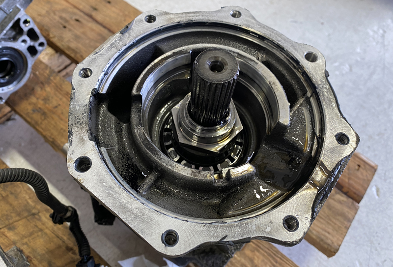
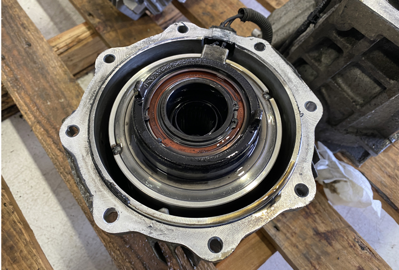
Splitting them in half to separate the clutch housing and gear housing, we can see a splined connection that interlocks the two halves.
On the gear housing side, the pinion gears are retained by an internal nut, which is good because splitting the assemblies did not affect the pre-load on the bearings.
Let’s look at the clutch housing side. The clutch pack is retained by the external nut on the driveshaft flange; again, splitting the assemblies did not affect any bearing pre-load.
Things are looking great! And with that, we assembled the CX7 clutch housings with the Speed6 gear housings without issues!
Now to review: if you are doing this swap, you will NEED a CX7 rear differential assembly, but you DO NOT NEED a speed6 rear differential assembly. We only did that to learn and to get the LSD. You can use the CX7 as is because the gear ratio is the same, and the LSD is not required.
Next up are the suspension trailing arms; when using the OEM Speed3 suspension, the trailing arms need to be modified to use the OEM CX7 wheel bearings.
Modifying the Trail Arms of the Mazdaspeed
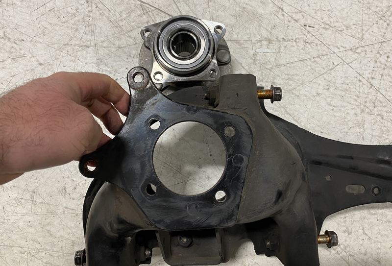
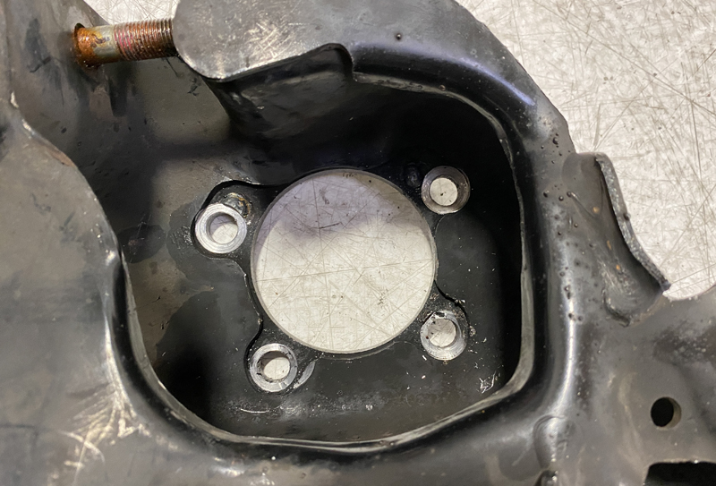
The OEM trailing arm has a beefy steel plate welded to the stamped steel structure. While the bolt and center holes look correct, they are slightly different in bore and location.
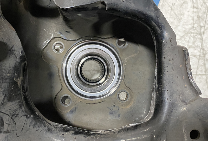
To make the Mazdaspeed 3 trailing arm work, modification was needed via welding the original bolt holes shut and then redrilling the holes in the correct bolt pattern for the CX7 wheel bearing. Along with that, the center bore diameter had to be increased slightly as well.
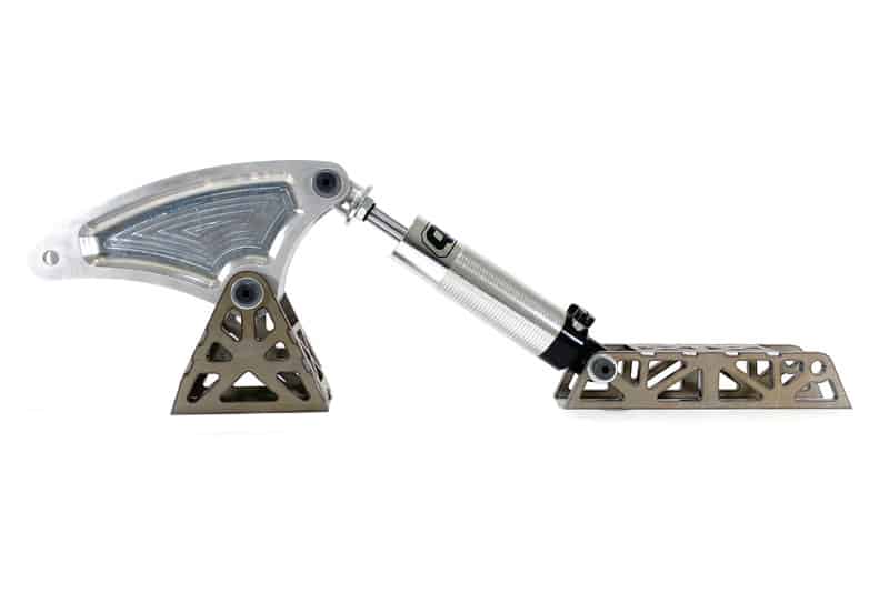
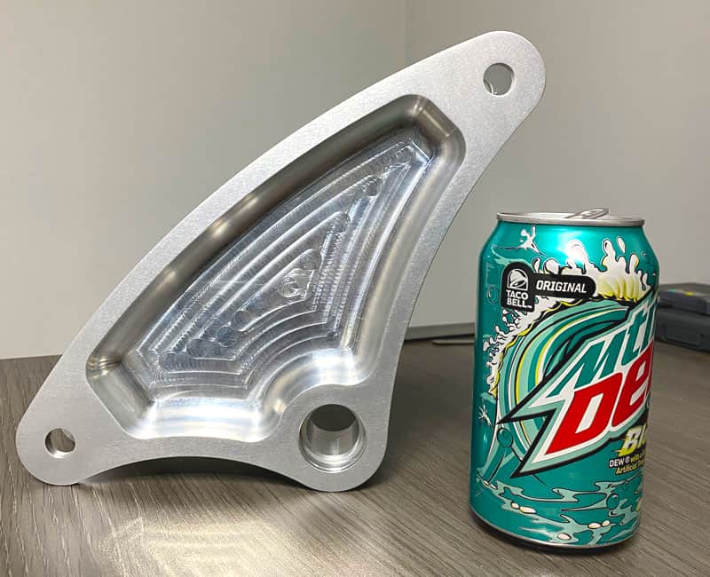
Modifying the rear trailing arms is only 1 of 3 major fabrication projects needed for the AWD swap. The others are building a Rear Motor Mount (which I designed a badass billet one for) and the center driveshaft mounting plate which I also designed.
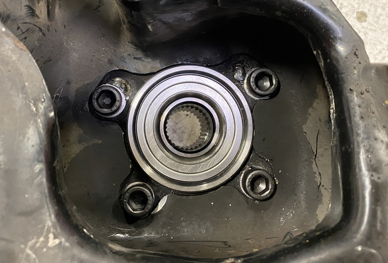
Now, with the trailing arms and wheel bearings in place, we can finally figure out the rear axle lengths. Checking both the Speed 6 and CX7 rear OEM axles, I found they use the same wheel bearing and differential inputs, which is great. However, The lengths are not the same.
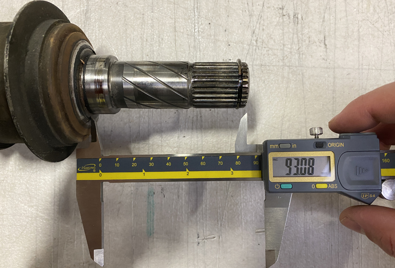
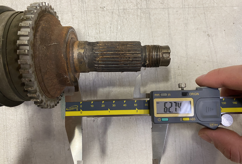
Unfortunately, in test fitting the Speed 6 and CX7, we found that both needed to be shorter for the Speed 3 application. With that fact, the cost is a lot more expensive for anyone swapping because of the needed custom rear axles.
I was personally going to get custom rear axles either way due to the power levels and use of the Halfmilespeed3, but it’s not a requirement.
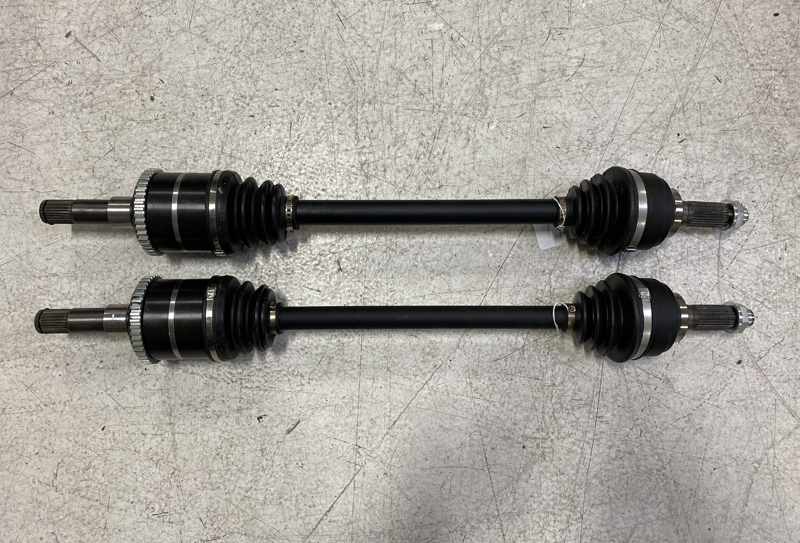
Fast forward many weeks, and we have a set of custom-length 700WHP-rated rear axles to compliment the front DSS 5.9 axles.
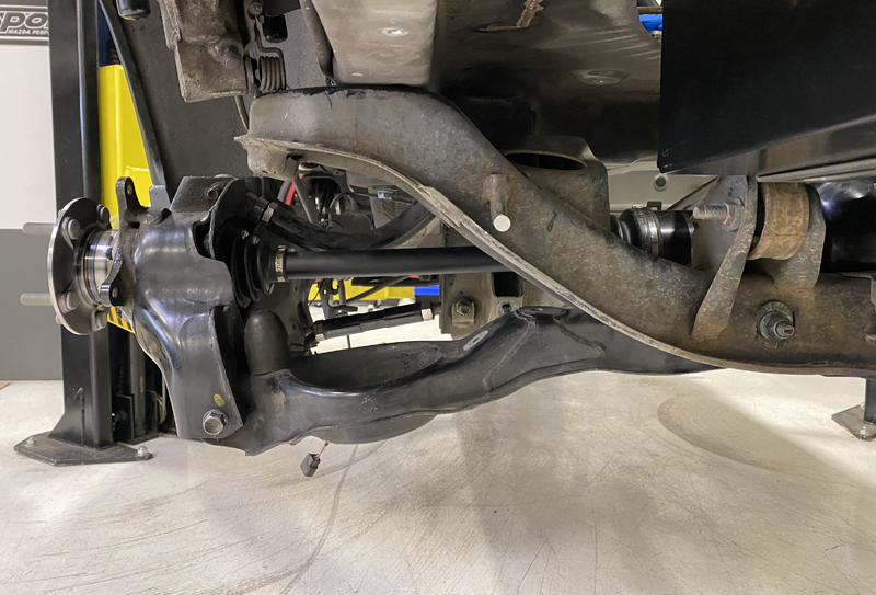
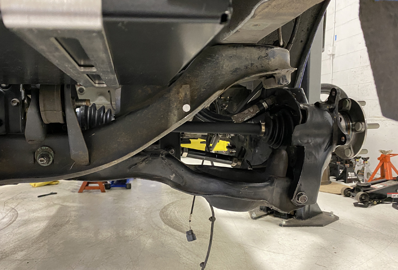
All bolted in and looking great! While doing this I learned a few things and realized that one of my assumptions was wrong.
- The front axles work and don’t work from the MS3. The driver front MS3 axles will interface perfectly with the Mazdaspeed6 transmission. However, the inboard CV housing/spline section for the passenger side front will need to be replaced/modified to work with the speed6 intermediate shaft.
- The rear ABS sensor for the Mazdaspeed3 will not work with a Speed6-style ABS trigger wheel. They use a much different and more modern magnetic trigger wheel incorporated in the rear ABS sensor for the Mazdaspeed3 will not work with a Speed6-style ABS trigger wheel. They use a much different and more modern magnetic trigger wheel incorporated inside the wheel bearings…which we don’t have when using the CX7 wheel bearings. This has led me to develop custom ABS trigger wheels to work with the OEM Mazdaspeed 3 sensor. More on that later.
Alright, that wraps up the rear drivetrain setup. There are plenty more huge milestones to overcome, which are coming up in this multi-part blog series!
I hope you are enjoying this series about the Mazdaspeed 3 AWD Swap. Stay tuned for more blogs to come!
You can also find updates on my IG @halfmilespeed3, the CorkSport 7th Gear Membership, and on mazdaspeeds.org.
Thanks for tuning in!
-Barett @ CS
Connect with us
You may also like
- How To Build A 900 Mazdaspeed 3 AWD Swap – Rocker Arm Suspension (Part 4)
- How To Achieve 400 WHP In Your Mazdaspeed
- Mazdaspeed High-Pressure Fuel Pump Rebuild Kit