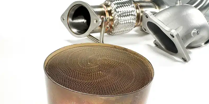
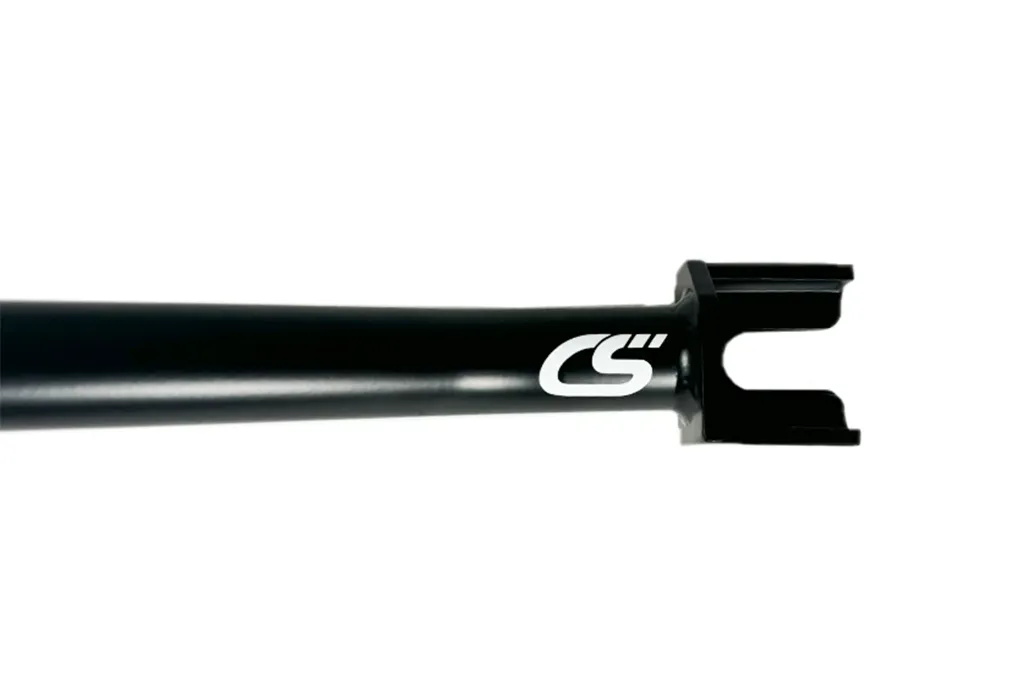
Unleash the potential and growl from your car and take the step forward into more power! A full 80mm Turbo Back exhaust is now possible with CorkSport’s new Catted Turbo Downpipe for the 2021+ 4th Gen Mazda3 Turbo (as well as CX30 & CX50 Turbo Models)!
Our downpipe uses a two-piece design, making installation easy without the need to wrestle with a single large, cumbersome pipe. The Downpipe starts with a high-flowing cast 304 Stainless Steel Bellmouth, then joins the 80mm mandrel-bent piping with a V-band connection for a leak-free seal.
An updated high-flow catalytic converter is utilized in our V2 downpipe. Our V1 downpipe used a Euro 3 300cel catalyst that showed mixed results with check engine lights (CELs). Our new and improved V2 unit uses a Euro 6, 500cel catalyst for the best in emissions control while minimizing those pesky CELs. Euro 6 is (generally speaking) a more strict set of emission parameters than in the USA. We also went for a more dense catalyst (500cel), which, when combined with an upsized 5” diameter, showed no significant power difference from the V1 300cel or even a fully catless prototype unit (catless not available).
The updated catalyst has shown no check engine lights through our testing. We cannot guarantee no CELs as testing all possible climates, driving conditions, local fuels, elevations, and any and all combinations of these is nigh on impossible! However, we are happy to report no CELs through ~10 months and ~14,000 miles of driving!
Do I Need A Tune?
Addressing the other elephant in the room: Tuning. We highly recommend getting a tune after installing the 80mm downpipe as there are very strict airflow limits in the stock tune that severely limit power. This will result in some mild stutters, surging, or “hiccups” at wide-open throttle. This does not do any damage as it is simply a very conservative safety limit for stock components.
With more flow-efficient parts (i.e upgraded intakes , Turbo Inlet Pipe, and exhaust systems), these limits are being reached much easier and the ECU will limit the power output of the engine. The vehicle will be drivable on the stock tune and still give you an aggressive growl out of your 2.5T!
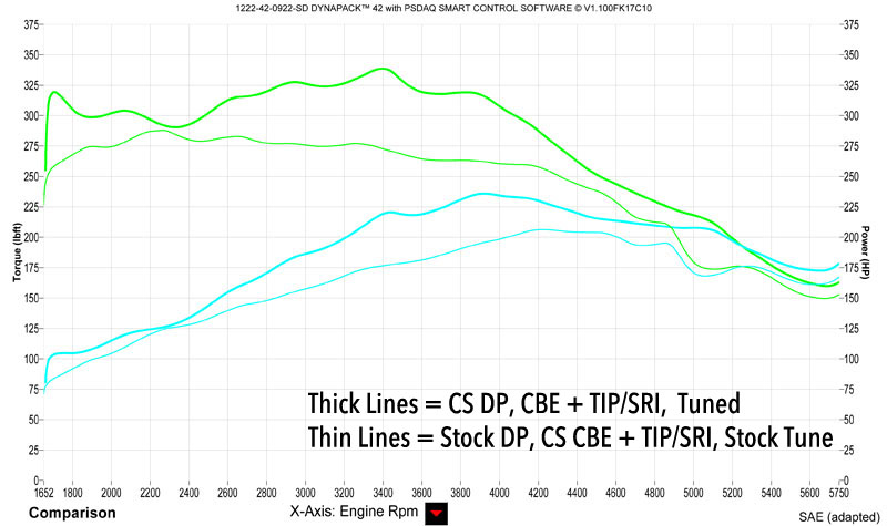
Here you can see the power gains with a fully-bolted Mazda 3 Turbo that is tuned vs stock downpipe and stock tuning.
Dynograph of the Mazda 3 Turbo Downpipe with CorkSport CBE, TIP/SRI – Tuned vs Stock Downpipe + CorkSport CBE, TIP/SRI – Stock tune.
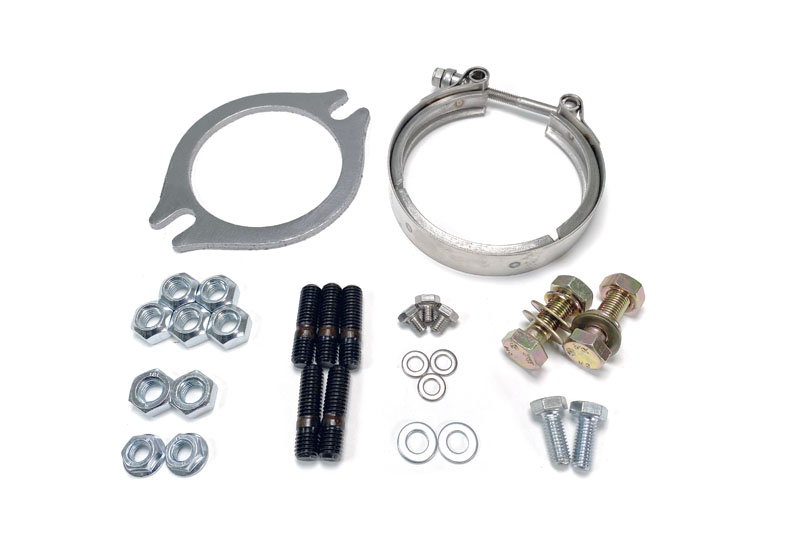
Each Downpipe kit comes with a complete pack of all the hardware and gaskets needed for installation. This includes:
Introducing the CorkSport Lower Tie Bar for the AWD 2019+ Mazda 3 & AWD CX-30! Improve your cornering characteristics and steering feel by stiffening the front subframe of your vehicle.
For example, anytime chassis bracing is added, the stiffened subframe/chassis allows the suspension and tires to do their job better, giving you the performance and feel you want on a twisty backroad. We are proud to bring one of our favorite simple Mazdaspeed 3 mods to the 4th GEN Mazda 3 and CX-30 communities!
Improved Handling
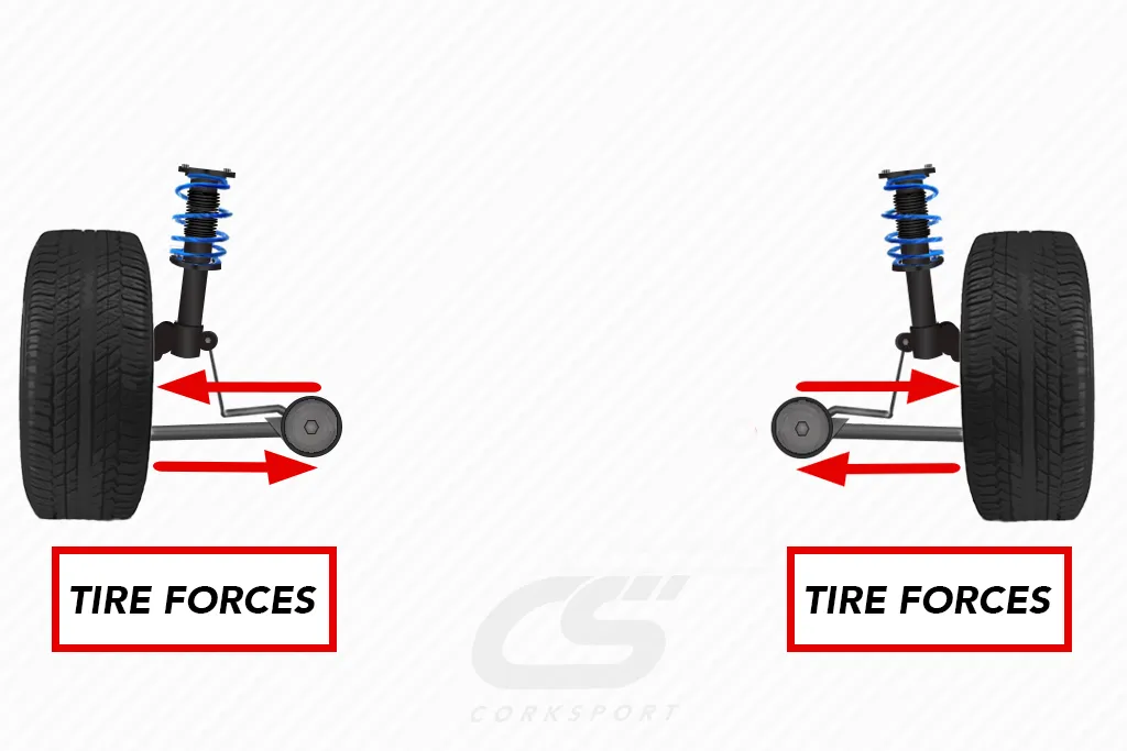
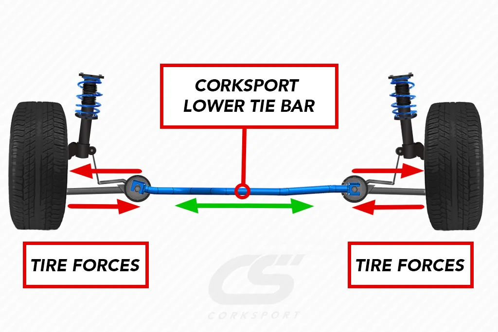
While cornering or under heavy acceleration, all the forces that come from your tires must be counteracted by the suspension and chassis of your vehicle. With lateral cornering loads, a lot of these tire forces are transmitted into your subframe. ( See Image Below) The red arrows show the forces as they act through the control arms and into your subframe.
How It Works
Since the 4th GEN subframe is essentially a large square, these forces can flex the subframe, pushing in the sides and/or turning the square into more of a parallelogram. This flex will dull your handling feel and slow the vehicle’s response to steering inputs. The CS lower tie bar connects the lower control arm mounting points, stiffening the subframe and allowing the CS bar to help counteract any forces that were flexing the subframe previously!
Drivers Report It Handles Better
Okay enough theory, what does this mean for your car? We tested opinions of the car with and without the tie bar, and our drivers reported good improvements! Specifically, better steering feel, reduced bump steer, and more responsive turn-in. The upgrade is perfect for driving on the street, track, or autocross! There is a minor enhancement to the brake pedal feel when under hard braking. Like on the MS3 lower tie bar, the CS GEN4 lower tie bar will even help to control wheel hop and torque steer during those hard launches.
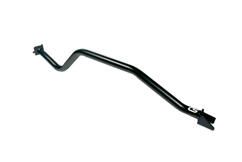
Shape of the Lower Tie Bar
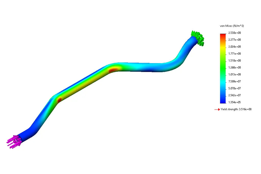
While the shape appears a bit unconventional for chassis bracing, it is for a simple and good reason: so the bar will actually fit! The clearances around the engine, transmission, and transfer case are pretty tight on the GEN4, so the bendy shape had to be used. Rest assured, it fits without issue and installs in just about 30 minutes! This design did present an issue: a bent bar will be less robust than a straight bar. Don’t worry; we used FEA software to simulate a high-load corner and found that our design is more than strong enough to take all of the forces directly without issue. This is a worst-case-scenario as in reality, these cornering forces are distributed among the suspension components, subframe, and rest of the chassis, but we felt it necessary to prove that the CorkSport lower tie bar can handle whatever abuse you can throw at it!
Testing the Tie Bar
Like our Mazdaspeed 3 tie bar, the 2019+ MZ3 bar is made from 1-inch diameter, 0.120-inch wall steel tubing with 0.190-inch thick mounting brackets on the ends. The material and same design philosophy have proven to take every bit of abuse on 600, 700, and 800 horsepower MS3s so you can be confident in its reliability on your GEN4! Each bar is finished off with a satin black powder coat and a small CS decal for a great-looking bar that will stay looking great for a long time.
While not required, the CS Lower Tie Bar works even better when paired with our other chassis braces, like the CS Strut Tower Bar, Sway Bar, and Mazda 3 Rear Hatch Brace. Check out our listing linked below for more info, and be sure to give us a call with any questions!
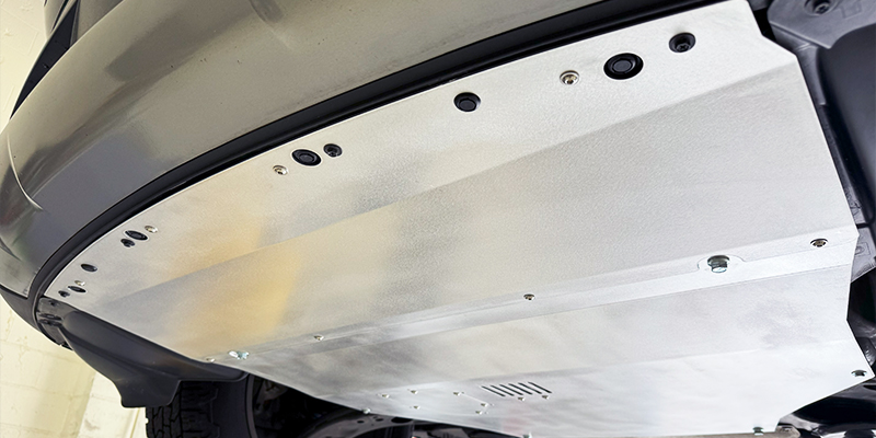
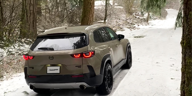
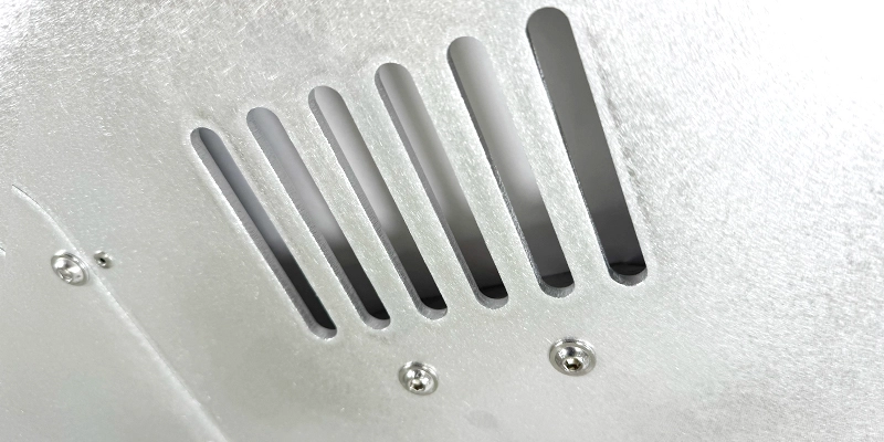
Traveling off the beaten with your Mazda CX-50 just got a whole lot better with the CorkSport Skid Plate. The new skid plate ensures you make it there and back again with the engine and transmission properly protected for all your on trail adventures.
Featuring an extra thick 5mm aluminum main plate that will withstand substantially more abuse than the factory plastic piece and an optional front plate for complete coverage, provides a substantial improvement to the OEM tray. So, if you plan on venturing off-road or want more on-road protection and peace of mind, keep reading below for more details on the CS Skid Plate for the CX-50.
From the factory, the CX-50 comes with a basic plastic splash shield/aerodynamic cover as found on other Mazda models. They provide the minimum protection needed for everyday street driving, but they are absolutely insufficient when faced with highway debris, through mid to extreme snow conditions, or more adventurous driving on forest roads.
When driving on these less traveled roads and trails, the probability of encountering large rocks or tree limbs is much higher and thus exponentially leading to the probability of damage to the underside of your CX-50. The damage that these objects can do to critical components, such as the oil pan, is a major concern, as it can leave you stranded.
The primary purpose behind the CorkSport Skid Plate is to better protect the engine and transmission from these potential threats. This allows you to traverse trails and forest roads with more confidence and helps ensure that you will get back home safe.
The CorkSport skid plate has multiple options so you can choose how much protection you want for your CX-50. The OEM splash shield is made up of two pieces: (1) a main rear section that covers the underside of the engine, transmission, and transfer case and (2) a front section that sits underneath the front bumper and radiator.
Option 1 of the CS skid plate is a replacement rear section only. The thick 5mm aluminum plate protects the critical drivetrain components while integrating with the plastic OEM front section.*
Option 2 of the CS skid plate replaces both sections of the OEM splash shield. It includes the same thick rear section but also includes a thinner front section (The same 2.25mm material used in our other skid plates). The front section offers much better protection for the radiator and front components than OEM, but the thinner material reduces added weight.
*Don’t worry, though; you can always start with the rear section and upgrade to full front & rear coverage later with our upgrade kit!
The design of the CorkSport Skid Plate is modeled after the factory shape of the OE cover to ensure proper fitment and coverage of the underside of your CX-50.
We changed where the skid plate attaches to the vehicle for sturdier mounting. We use aluminum standoffs in four key locations that allow for M10 hardware to be used instead of the OEM M6 hardware and push clips.
A slight modification is required if you install only the main CS skid plate, as two holes must be drilled in the plastic OEM splash shield to accommodate the new mounting points. This does not cause any issues if you decide to go back to the OEM splash shield at a later date. Good news, though—if you chose both sections of the CS skid plate, no permanent modifications are required for installation!
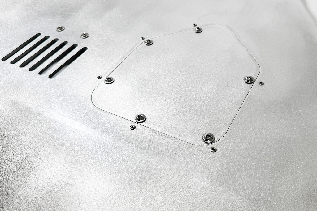
We were careful to incorporate all of the features of the OEM splash shield as well! This includes an air duct to keep the transfer case at the proper operating temperature when you are out on the trail (just like OEM).
We also designed a recessed oil change access panel to provide protection to your oil pan while allowing for quick oil changes without full skid plate removal. The oil cover is flush with the rest of the skid plate, providing a near-seamless transition between the main plate and the oil cover, so there is little chance it can get snagged on anything that you may drive over.
The 5052 aluminum that we picked for the CX-50 Skid Main Plate is the thickest we have done to date. At 5mm or just over 3/16in, this skid plate is over double the thickness of our other skid plate fitments to ensure that it can withstand extreme conditions.
To get its shape, the CorkSport Skid Plate is laser cut and then precision bent, which provides a quality fit and finish. The optional front plate is made out of our standard thickness of 2.25mm (~0.090in) aluminum, with the same laser cut and bent process.
All necessary hardware is included for installation and our electronic instructions are conveniently located on our our site, so you can discover new trails in no time.
If you are searching for increased underbody protection the CX-50 Skid Plate can provide, head on over to the product listing for additional images and details. As always, if you have any questions, don’t hesitate to call!
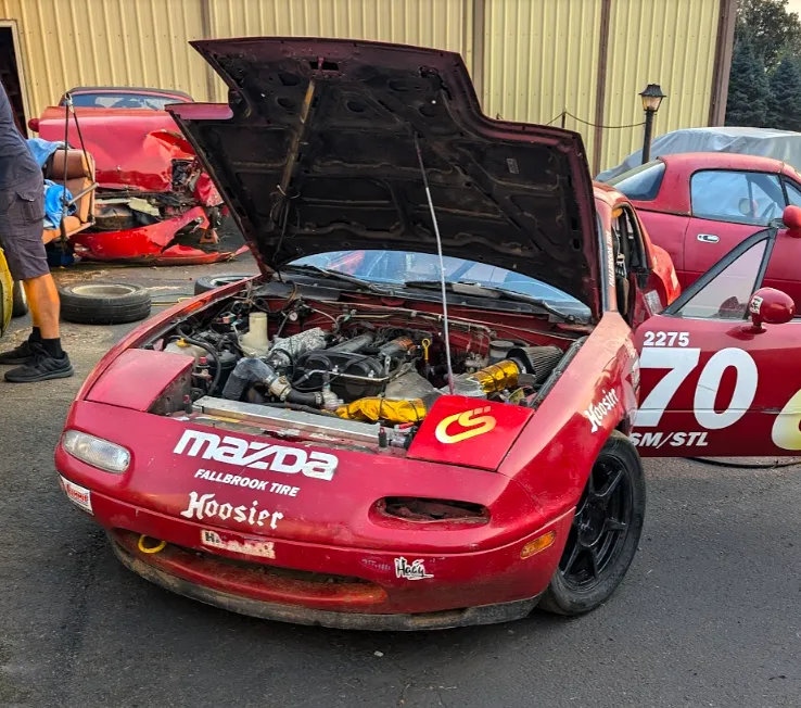
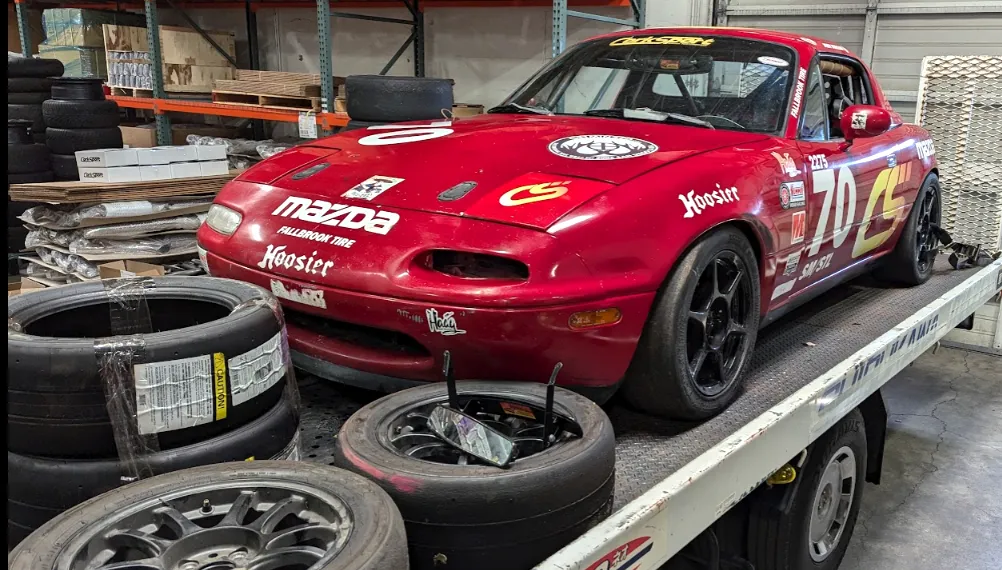
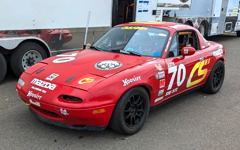
CorkSport is happy to announce touring car availability for those people/teams who want a fun-to-drive and great-looking race/track-focused Mazda 3! The goal of the build was to make a competitive and reliable TC race car and get Mazda back into multi-make competition, which goes back to the Speed Vision and World Challenge days of the early 2000s.
For the 2024 season CorkSport has been validating the design work and lessons learned racing the CorkSport Mazda 3 TC in the SRO TC America TC class. We had multiple podium finishes and ran at the front proving the competitiveness of the Mazda platform against the Hyundai, Honda, and Mini TC class cars.
The base of the build is the Mazda 2.5 Skyactiv engine with a CorkSport bespoke turbo kit developing well over 300 wheel hp in TC trim. The TC car engine management is handled by a Motec M1 ECU, in conjunction with a Bosch Motorsports LC2 wideband controller, and a Motec C125 dash/logger.
The 6 speed Mazda gearbox is equipped with a clutch type LSD and upgraded 3-4 gears with a transmission cooler, while the clutch is an off the shelf X-Clutch single disc clutch/flywheel combo.
Penske shocks/Swift springs, CorkSport upper mounts, and upgraded suspension pick-up points handle road racing while allowing for accurate suspension settings.
Braking is handled by a 364x32mm 6 piston CorkSport race brake kit which uses floating front rotors paired with upgraded rear pads and brakelines on OEM calipers. The brakes are covered with 18×10 Enkei lightweight RPF1 wheels.
To top off the build is the widebody kit which includes, front bumper, splitter, front and rear fenders, side skirts, rear bumper and TCr spec rear wing.
SRO Circuit of the Americas 2024
There is limited availability for the start of the 2025 race season. Currently 2 cars are left for delivery early 2025 for the 2025 TC America race season.
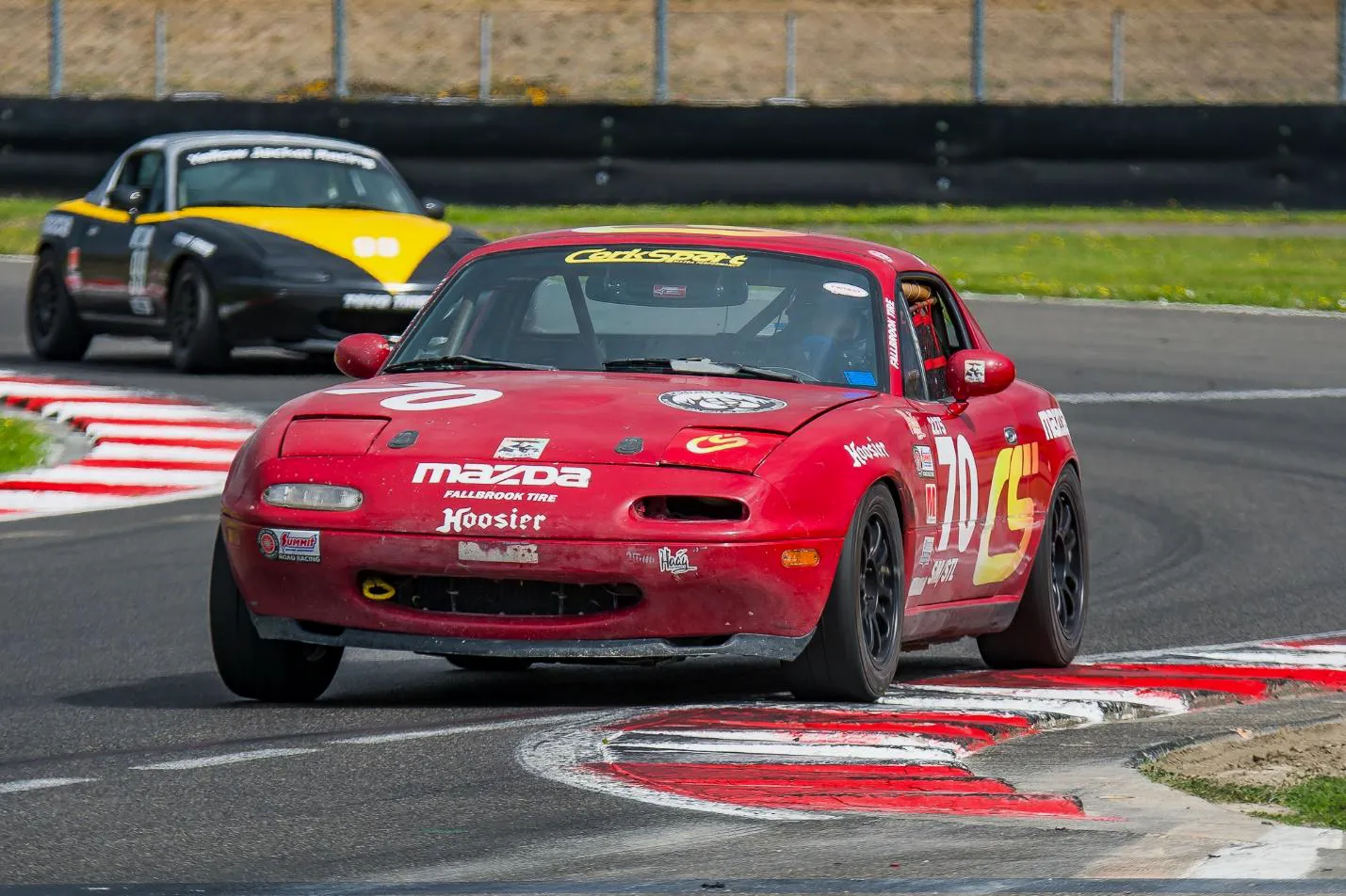
A few years back, I had grand plans of going Spec Miata (SM) racing with a good friend in southern California during the winter months, intent on improving my on-track driving and racecraft overall. After the 1st event, things changed as my friend passed away.
My SM was only raced a few times during 2022 season, but after that, it was parked along with its fellow spec Miatas.
I brought the car back home in December 2023 along with an additional spec Miata on the trailer – with the intention of racing this year. I finally got the car out of the trailer to start cleaning it up and making sure it was solid to race.
Besides cleaning the car inside and out, and ensuring all its safety parts were still good, the car was pretty much ready to go. The biggest challenge was cleaning up from the cheese bois, which made the trunk a party house for a while.
I had several sets of Toyo RR tires that had been purchased back with the grand plans that were made in 2021. They had been sitting in a trailer since then and baking in the California sun. I chose a few that looked like they may still be soft and signed up for the race weekend.
The Friday test day, gave me a few chances to remember how to drive this car fast, as it had been more than five years since I raced an SM at Portland Intl Raceway. I double-checked the alignment settings and headed off to my weekend racing adventure.
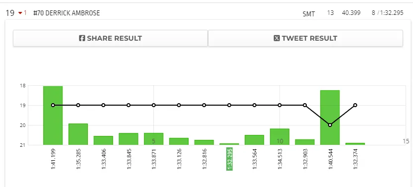
Test lap times were pretty slow compared to what I needed for the PNW Spec Miata Tour. I was turning 1:35 lap times, and if you want to be in the top ten, low 1:32s or better were going to be needed to get there. I focused on cleaning up the exits to turn 7 and 12, which lead onto the straights, as these were the sections of the track I was losing time according to my lap timer.
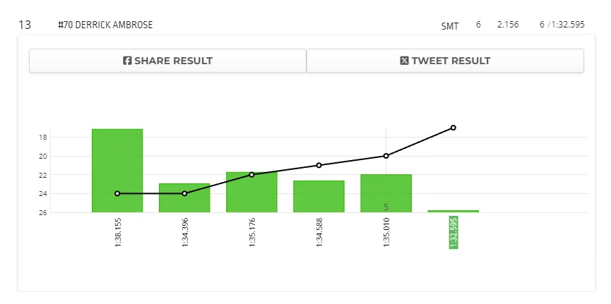
After consulting a few friends about the tire pressure settings and how to close up the gap, I headed out Saturday morning in qualifying to see what I could do. After dealing with a bit of traffic, I got some breaks from people who let me through, and I hit a 1:32.595, which I felt was about as good as I was going to get, so I called it quits for the sessions.
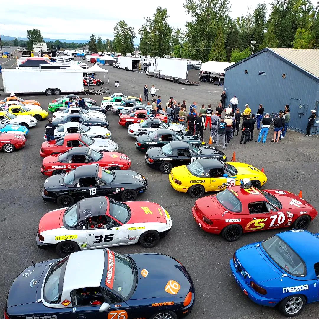
After a quick driver’s meeting and 30 minutes doing a nut and bolt check, I was ready for the afternoon race, which is a 25-minute affair. I have been racing for ~13 years now, and it is fun how you still get the butterflies heading around the last corner in double formation for the start heading for the green flag.
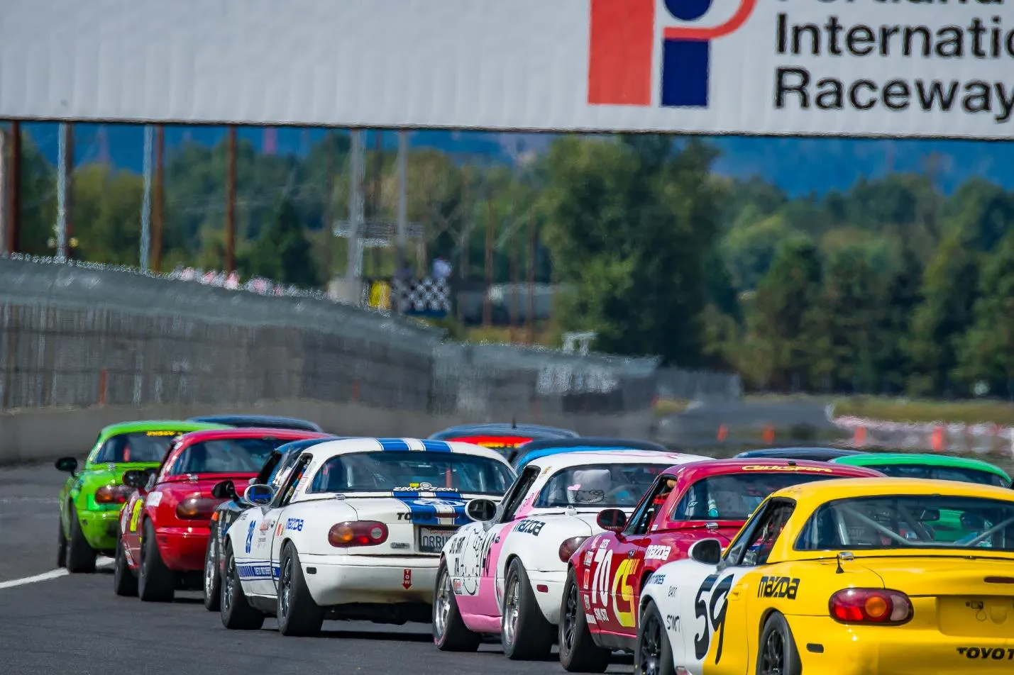
The starts at PIR, as always, are pretty wild mid-pack, and everyone is trying to get an edge on everyone else around you. I made it through the first corner without hitting or getting hit and proceeded close up on the car in front of me as much as possible.
During the race, I noticed that the car felt a little numb on feedback, and I found myself waiting for my Miata to respond to inputs. Waiting is relative, as I am talking about milliseconds, which seems like forever when racing cars. There were plenty of spots swapped, people spinning off the track, and great race action!
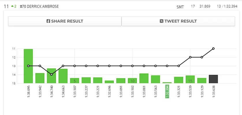
I started in 13th, and by keeping it clean and on track, I made it up to 11th place when the check flew. My goal was to be in the top 10, so I was pretty happy that I ended up 11 out of the 32 cars that had signed up for the weekend.
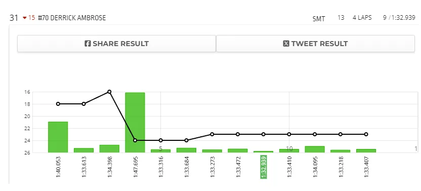
I also improved my fastest race lap, which means I would start higher up the field. I wasn’t the only one who was faster, so starting on Sunday for race #2, I was in 18th, and it was all downhill from there…
Race 2 TL;DR
I spun a few times and lost one spot overall during the race. Long version, the “wait” for the front end to turn was getting worse as the race progressed. There wasn’t a lot I could do with that so it was a race full of trying to drive around my problem by braking in different areas and turning in early to try to hit the apex and marks to make the corners.
Race 3
I got to start in 18th place again, as no one made up any more time/places in order to change the starting position in the middle of the field. The start went okay, and I didn’t make up or lose any spots as the field sorted itself out.
Lap 4 I went up the inside of another driver into turn 4 and lifted as I felt the car start to slide out. This was the wrong thing to do as it upset the chassis as I was ½ on a curb and ½ on the track, so around I went off into the grass. I felt a little boop from the other driver I was passing as he bailed out. I got stopped before the tire wall and headed back on the track now in 24th position. I was able to get a pass on another car and get back to the 23rd position, but I was really struggling to get the car to bite on the front-end grip.
Lap 13, heading into turn 1, aka the chicane, the car pitched more into the corner than I expected, and I looped it. I got going again and in turn 4 the car cut out briefly which means I was running out of gas. I limped it back into the paddock and called it a day.
I made sure to go talk to the other driver, which I failed to execute the pass on, and apologized for dragging us both off into the grass. He was pretty cool about it, but his wife gave me the stank eye the whole time. There is not much you can do but go say sorry, and he was happy with that. I would be if I were in the same position.
The fuel calculation miss was all on me. You usually run a specific amount of fuel per lap and toss in some extra for wiggle room. I did not put any wiggle room in the SM, so I ran out.
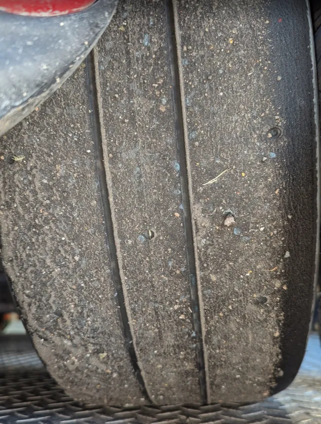
The front-end grip problem was due to the tires. When you usually get off track, you can feel the heat from the wheels and tires. After many sessions, you can barely touch the wheel because the heat is being transferred from the brakes to the wheels and the tires. The tires are normally very warm/hot to the touch after coming off the track. The Toyos were barely warm, which means they were not hitting the operating temperature, which is needed to generate maximum grip and allow me to do what I wanted to with the car.
The picture above of the left front tire from the car after 3 test sessions, a qualifier, and 3 races looks like it has been out for a warm-up only. The left front tire takes all the abuse at Portland, so it should show signs of heavy wear. The racing season is over for the Northwest, so I will be sure to get some newer tires on the car next season.
Want to race Spec Miata with the rest of the NW people? The PNW Spec Miata tour page is NWmiata.com. Shout out to A-Aron for hanging out and watching me spin off the track and having a good time doing race car stuff.
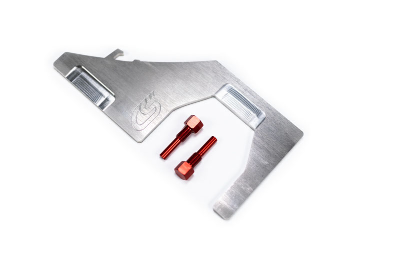
Have you ever seen a timing kit with an integrated bottle opener? I didn’t think so! We here at CorkSport know that when replacing the timing chain or installing other modifications that require you to time your 2.3L DISI MZR engine, something cold and refreshing is a must-have. That’s why we chose to make the CS Timing Kit with a bottle opener so that it can be more than a tool that is just used for timing your motor.
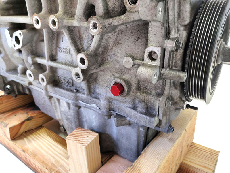
Included in the CorkSport Timing Kit, are two 6061-T6 aluminum crankshaft timing pins. The timing pin is used to set the number 1 piston to the Top Dead Center (TDC), which is a necessary step when timing the 2.3L DISI MZR engine – especially after replacing your refreshing Mazdaspeed 3 or Mazdaspeed 6 with a Mazda OEM VVT Kit!
We picked aluminum over Stainless Steel in this case because if the pin is accidentally left in after the motor has been timed and the motor is turned over, the aluminum pin will give way instead of damaging the motor which could happen if a steel pin is used. This is also why we decided to include an additional timing pin, so you’ll have a backup if needed.
Finally, we chose to anodize the timing pin in a bright red, so that is easily visible when installed in the motor so it doesn’t get left in by accident.
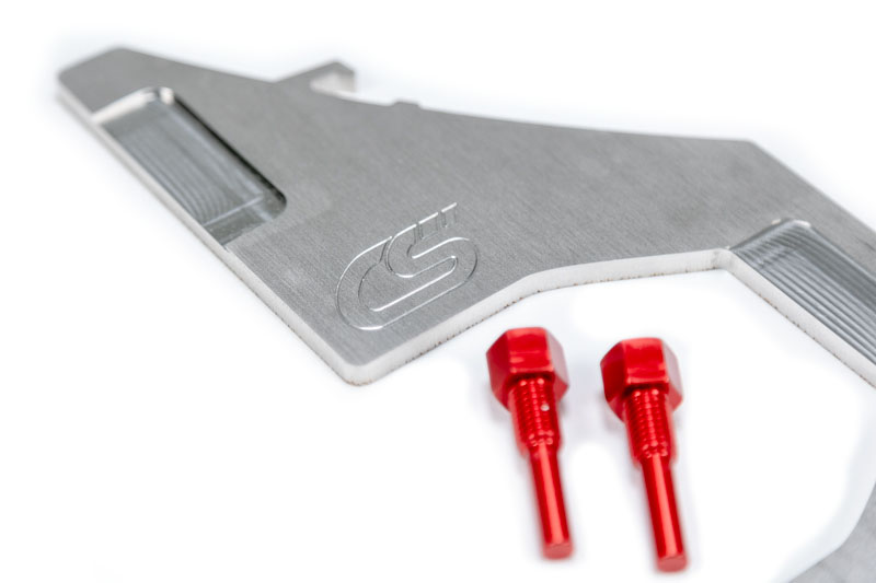
Also included in the CS Timing Kit is the cam alignment plate which is made out of 1/4″ 304 Stainless Steel to provide a long-lasting finish as well as the durability needed to ensure the pockets in the alignment plate stay at the proper specifications.
The cam alignment plate features precision machined pockets that are used to align the cams ensuring a tight and accurate fit. The purpose behind using a camshaft alignment plate during the timing process is that it is used to locate the intake and exhaust camshafts so that they are properly synced with one another.
After the cams have been properly aligned with the timing plate, the camshaft gears that connect the timing chain to the cams can now be tightened using the wrench flats built into the cams to hold them in place while you torque down the cam gear bolts.
Even though similar timing tools have been out for a while, the main goal behind the CS Timing Kit was to provide anyone with a 2.3L DISI MZR engine, a single place where you can get both the Mazda OEM Timing Chain Kit and the tools necessary for the job. We hope that the CS Timing Kit helps gets your 2.3L Mazdaspeed back up and going in no time.