CorkSport Mazda6 2.5T Boost Tube

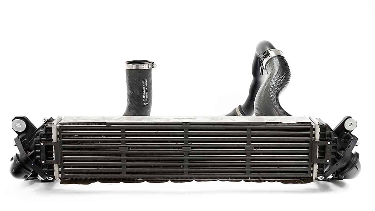
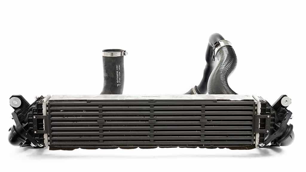
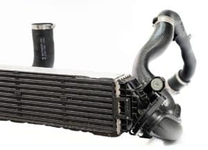
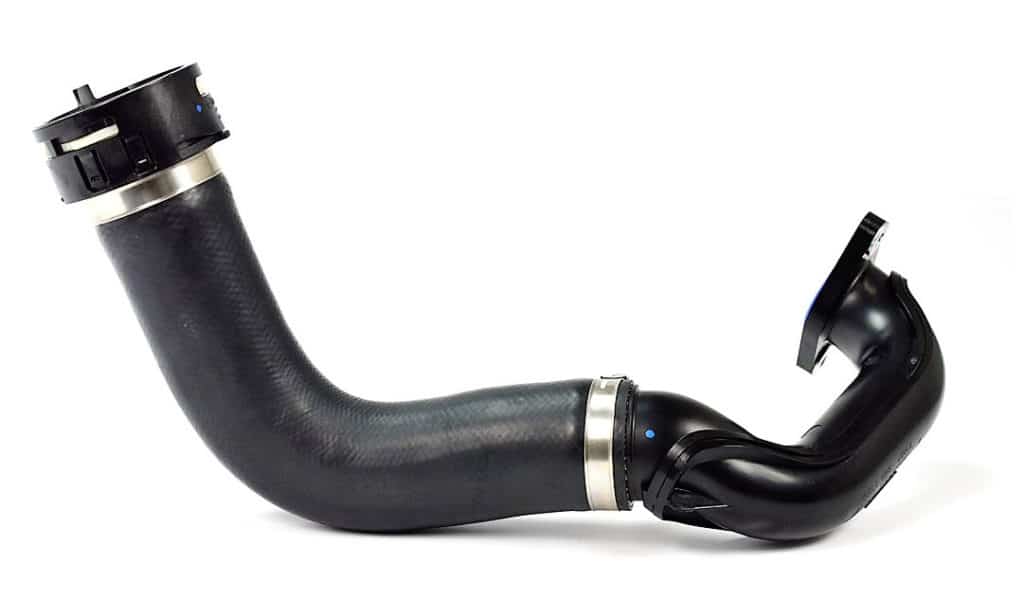
We are proud to release the CorkSport Upgraded Boost Tube for 2018+ Mazda 6 2.5T and 2016+ CX-9 2.5T. The CorkSport boost tube is larger, stronger, more reliable, and of course better looking than the OEM rubber tube. Increase throttle response down low, hit boost targets easier and future-proof your ride for mods down the road with a simple 1-hour install. Read on for full details and be sure to check out the R&D blogs here and here for the backstory.

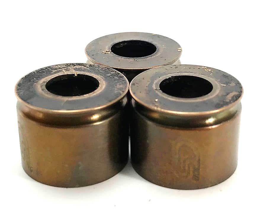
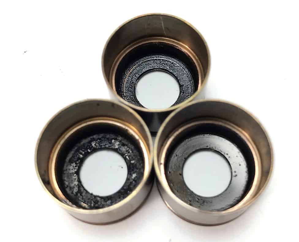
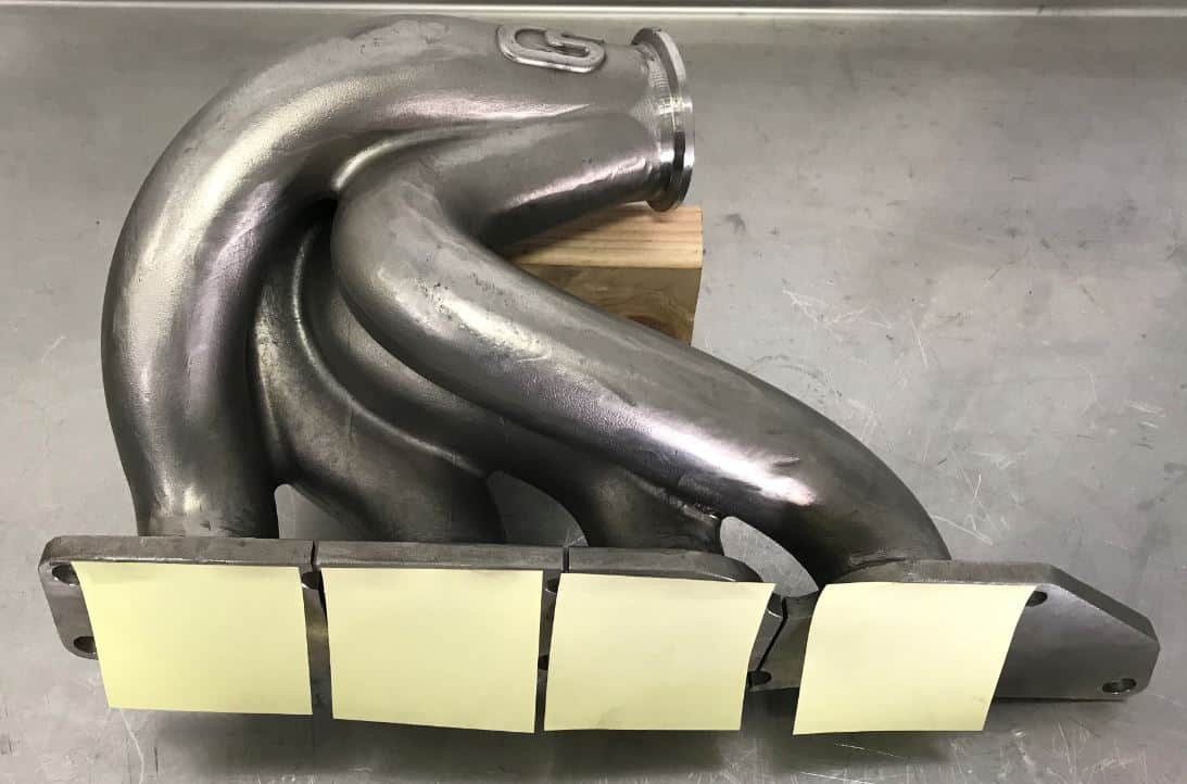
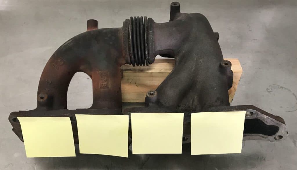
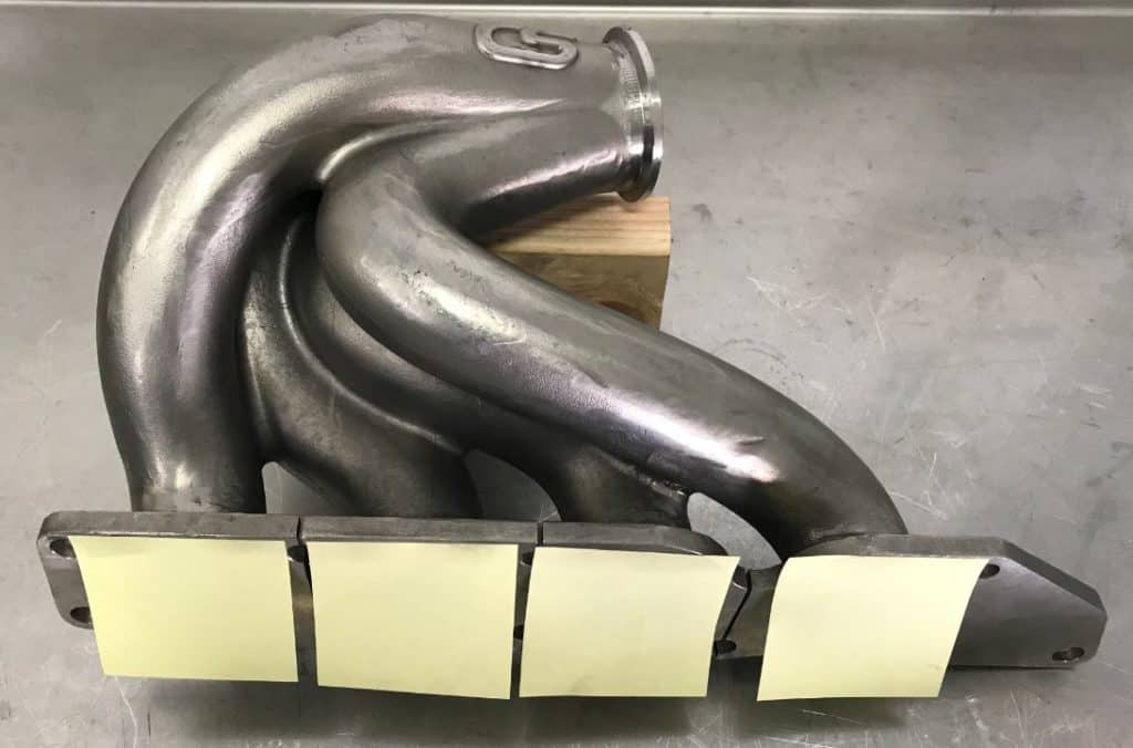
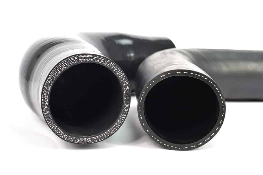
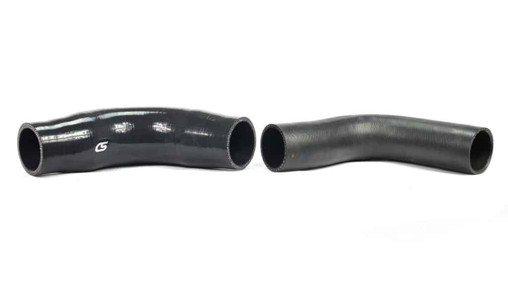
In case you haven’t read the previous blog installments, the CorkSport Boost Tube improves on the OEM boost tube by first strengthening the tube. Instead of using rubber with one reinforcement layer, the CS boost tube use silicone with 5 layers of reinforcement. Aside from the extra layers of reinforcement, silicone stays strong at high engine bay temperatures that may cause rubber to flex excessively. In addition, silicone lasts longer and will better resist cracking as your Mazda 6 Turbo ages. The OEM boost tube is made from materials very similar to the OEM Mazdaspeed 3 boost tubes that showed signs from aging extremely quickly, especially when subjected to higher than OEM boost levels. Cracking or splitting of the OEM tubes results in boost leaks and a poorly running car, definitely not what you want from your brand new SkyActiv 2.5T.

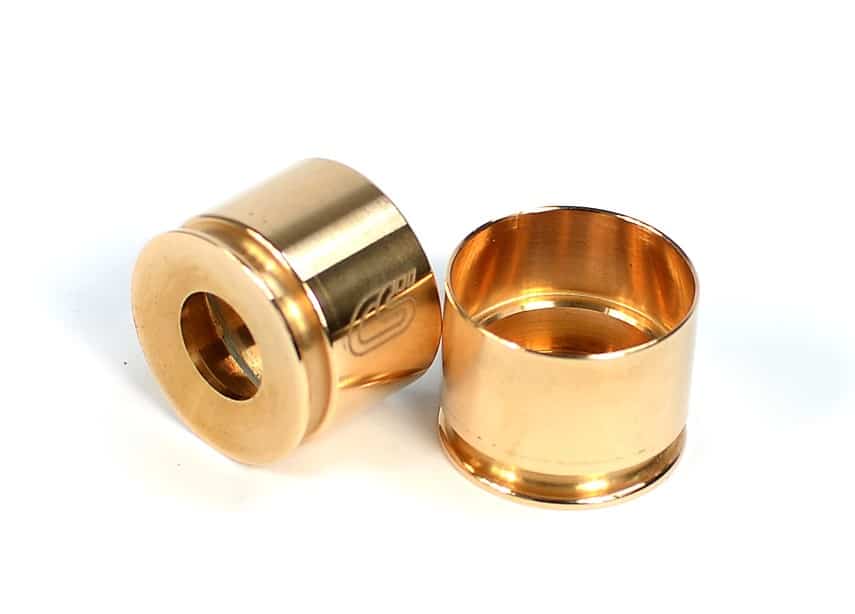
The added strength prevents the CorkSport Upgraded Boost Tube from expanding excessively when subjected to pressure. When pressure tested at 20psi (the largest pressure we have seen at the intercooler outlet), the OEM tube was shown to expand 12% at the internal cross-sectional area. The CS tube tested under the same conditions expanded 3x LESS. This difference would get even larger when subjected to the same pressure at a higher temperature. What does this mean for performance though? When you get on the gas, the boosted air will have to expand the tube before it can enter your engine. The less the tube expands, the easier it is to hit boost targets, and the better throttle response you have, especially down low in the RPM range.

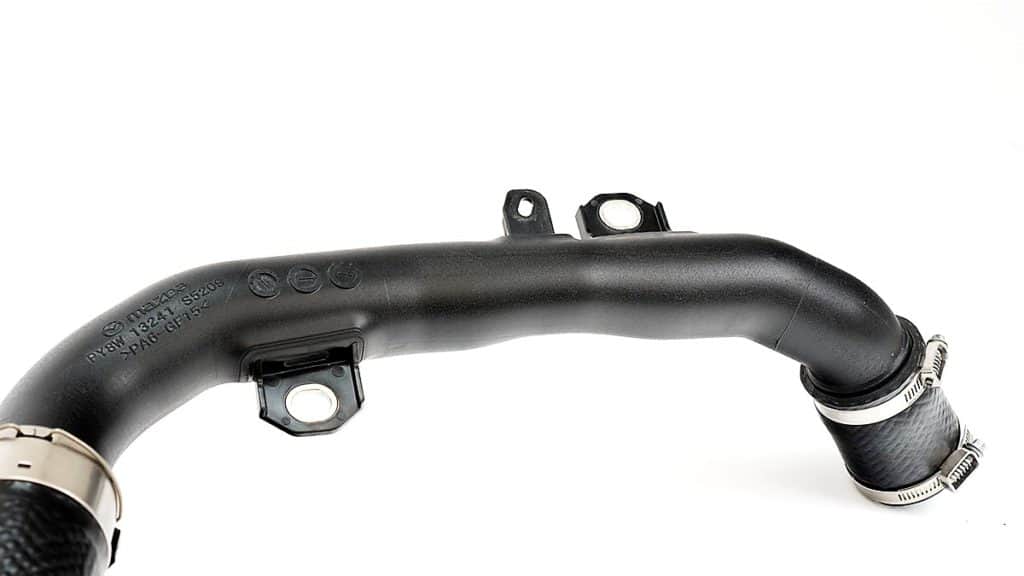
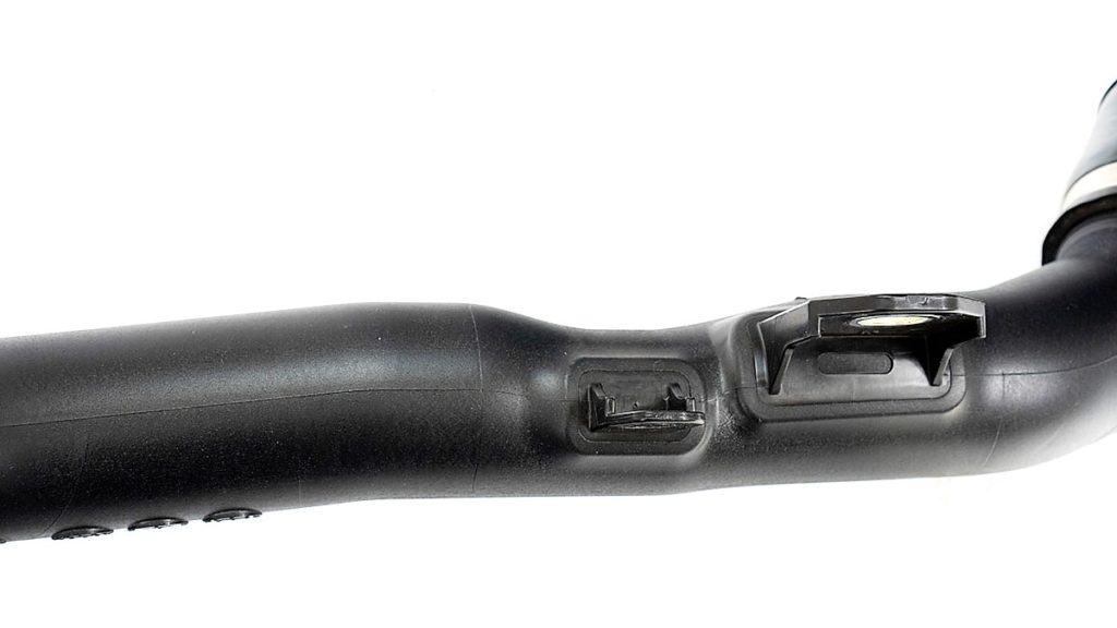
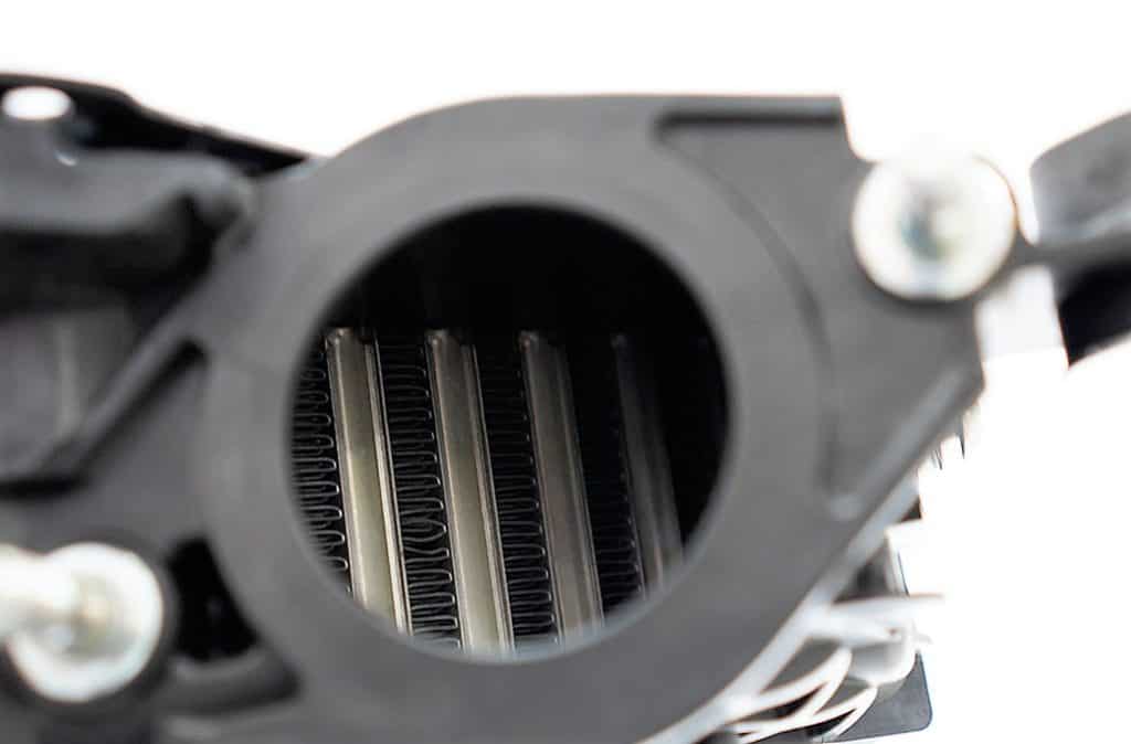
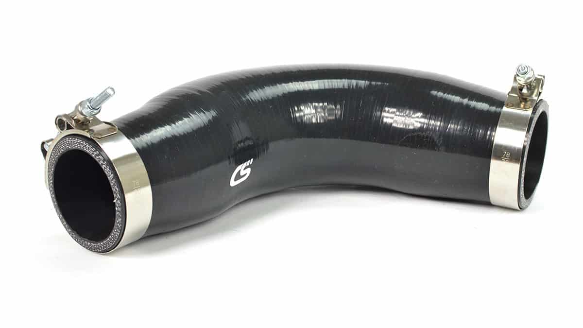
The CS Boost Tube also is a larger inside diameter than your OEM tube. It is 3” through the middle vs. the OEM ~2.44”. Since this area of the charge piping system is directly ahead of the throttle body, this large volume of air has the same effect as it does with our GEN2 Mazdaspeed3 FMIC kit, reducing boost lag and increasing throttle response. For full info on why this happens, check out the release blog for that kit here. As a basic overview, the large volume of air right before the throttle body fools the engine into thinking it has a larger intake manifold plenum than it really does. While not as severe of an effect with just changing this boost tube, try it for yourself and see what you think!

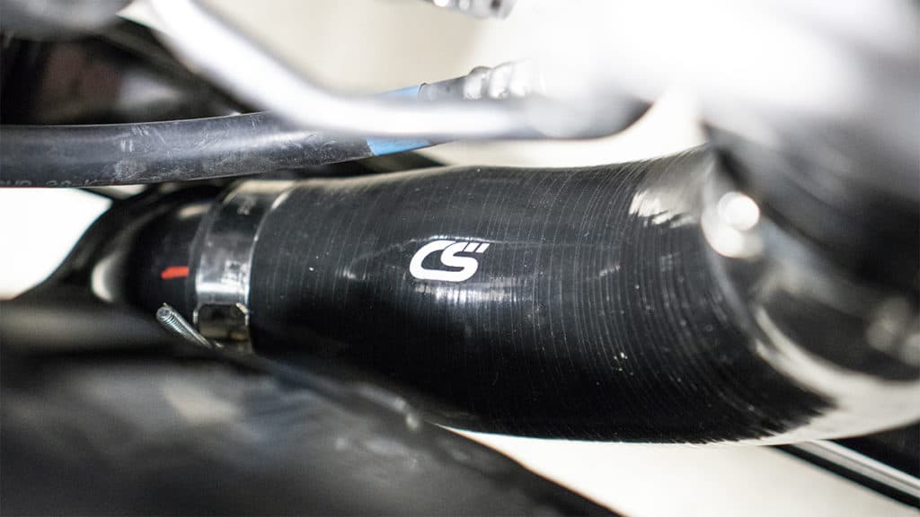
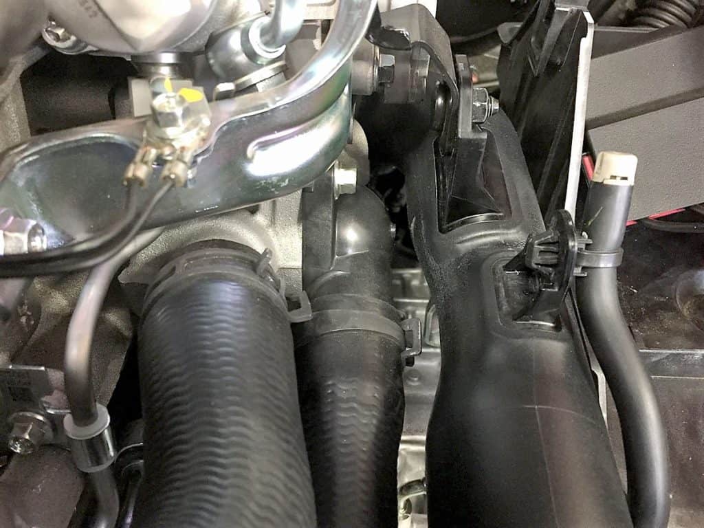
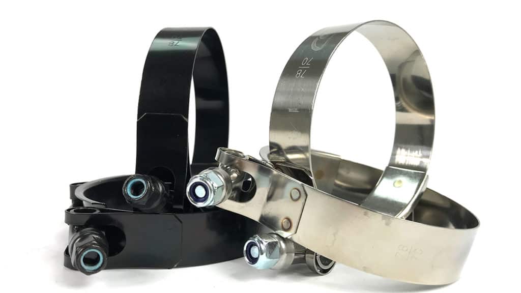
Installing the boost tube is a little tricky due to where it is located, but we include high-quality installation instructions to make it easier. Even so, it can be installed in an hour or less in most cases. We also include polished stainless steel T-bolt clamps to ensure a complete seal and add a subtle visual boost.

Be sure to check out the product listing for more pictures, the installation instructions, and a detailed product video. Let us know if you have any questions, we’ll be sure to help you any way we can!


Lastly, if any of you are looking for a more serious upgrade, stay patient, our FMIC upgrade & full piping upgrade kit are coming soon!

Stay up-to-date on the latest news and product updates from CorkSport.

* indicates required

MZR DISI Injector Seals – The Correct Seal for YOUR Speed

Many years ago we helped bring a revolutionary design to the Mazdaspeed community.  Fast forward 4+ years and you’ll find that the CorkSport Tokay Injector Seals are still the best option for your Mazdaspeed.  

Recently, we had a customer ship their stock block engine core to us for a fresh Dankai 2 Built Block.  During the engine core tear-down and inspection, we found a set of CorkSport Injector Seals installed.  We realized this was a great opportunity to share what we found with the community.

When the CorkSport Injector Seals arrive at your door they look like this:

Brand new a fresh of the lathe with all of their beryllium copper brilliance.  After many thousands of miles of use and abuse they look like this:

Now to the untrained eye you may think they look bad, but the truth is they look fantastic!  The visible top of the seal has a small amount of carbon deposits present. This is to be expected because this surface is exposed to the combustion chamber.  Moving to the side of the seal you can see a distinct clean edge and no carbon deposits on the sides of the seal. This distinct clean edge is where the exterior of the seal is designed to seal in the cylinder head.  This is awesome!

Now let’s look at the inside of the used seals:

Again we see carbon deposits, but they are in and only in the expected locations.  Moving up the side of the seal you can see a “shelf” or “step” that is clean. This is the edge that the fuel injector seals against. Beyond that the inside of the seal is clean.

From this inspection we can see that the injector seal was functioning as designed and doing its job effectively.  

So you might be asking…”What is so special about this design?” Well, we wrote a two-part design blog answering that exactly.  We highly suggest spending the 10 minutes to read these.

Injector Seals Design Part 1

Injector Seals Design Part 2

This is exactly why every single CorkSport Dankai Built Long Block includes a set of CS Injector Seals, but if you’re not looking for a built block but still want the assurance of the CS Seals you can check them out right here.  The install of the seal can be a bit tricky sometimes, especially getting dirty injectors out of the cylinder head.  Because of that we’ve developed an injector puller tool that makes the job MUCH easier.  

We hope you enjoyed this quick tech inspection of the injector seals!  Thanks for tuning in with CorkSport Mazda Performance.

-Barett @ CS

2018+ Mazda 6 2.5T OEM Intercooler & Piping Analysis

We’ve already mentioned briefly that we have an upgraded intercooler kit in the works for the SkyActiv 2.5T, but now it’s officially time to dive in and get into how and why a Mazda 6 upgraded intercooler kit is a good fit. To understand how to make a performance part, we first have to understand what makes the stock parts tick and where we can improve them, which is what we will be covering today!

For those of you that are new to the boosted lifestyle, I feel that I should go over a few terms that will be thrown around frequently later in this blog.

  • Hot Side Piping: Also known as just “hot side” or “hot pipes” this piping section carries the pressurized air (boost!) from the turbocharger to the intercooler. As it is before the intercooler, the air has not been cooled and the “hot” name is quite accurate (think 200-250°F. or even more on a turbo that’s too small). Shown above on the right side.

  • Intercooler: A basic heat exchanger. Air flows through the inside and is cooled by air flowing through the outside while you drive down the road. The same way a radiator works except with air inside instead of coolant. It is made up of three parts the “end tanks” and the “core”. The end tanks are what transfer the air from the piping to the core while the core is the actual heat exchanging portion. Shown front and center in the above image.

  • Cold Side Piping: Also known as just “cold side” or “cold pipes” this piping section carries the pressurized air from the intercooler to the engine. As it is after the intercooler, the air has been cooled to make more power. Shown above on the left side.

Now into the details…

The hot side piping must make its way all the way from the rear of the engine to the front of the car. The OEM piping takes a pretty direct route, and is a decent diameter for stock piping, starting & finishing at just under 2” inner diameter. This, however, is where the good things end.

To start, the two rubber sections of the hot side are single ply. These allow for good flexibility on install and to allow for engine movement but will start to expand on higher than stock boost levels, increasing boost lag and decreasing throttle response. In the image above, the main rubber section squishes under the small weight of the upper plastic section of the hot pipe. This isn’t even the main issue with the hot side piping!

The upper plastic section of the hot side has quite a few small radius bends, and a few areas where the pipe reduces in diameter severely, affecting the maximum flow and restricting the power of your 2.5T. Check out the worst area below, it’s tiny!

And what might be causing this reduction in diameter you may ask?


That’s right, its clearance for a hose clamp. Mazda, I’ve got to call you out on this one, couldn’t you have just rotated the clamp, and kept the diameter in the pipe? Anyways, on to the intercooler itself.  

The intercooler itself isn’t too bad, a decent sized core with lots of fins to help cool as good as it can. That being said, there’s still plenty of room for improvements. First: make it bigger. The intercooler mounting could’ve been simplified to get more width, and there’s a bunch of room to go thicker. While thick is not the best for heat transfer efficiency, it will still help cool off the air better. Height is already more or less maxed out without cutting up the crash beam, but we should be able to make enough extra volume elsewhere to make a big difference.

Intercoolers are a delicate balancing act between cooling efficiency and pressure drop. Cores that cool extremely well usually have a larger pressure drop (loss of pressure from inlet to outlet) and vice versa. With the high fin density of the OEM intercooler, we can expect a relatively high-pressure drop (2-4psi would be my rough guess) but pretty good cooling. From early dyno testing on the CorkSport Short Ram Intake, the intercooler does a good job cooling but loses power on back to back dyno runs. I expect that this is the intercooler “heat soaking”. Heatsoak is what happens when an intercooler is undersized or is not getting enough airflow, it heats up and is no longer able to cool the boost off, robbing you of power.

The two images above show the real Achilles heel of the OEM intercooler and what is likely causing the heatsoak issues: the end tank design. Since the charge air enters and exits the core at an upward angle, it’s being directed away from the lower runners of the core. There is a sharp angle that would be hard for the air to turn, meaning the bottom three internal runners (shown with the red box) are likely not actually doing much. So you’ve got intercooler taking up space that is likely not doing much… We aim to fix this.

The cold side of the system is actually pretty good-inner diameter of just under 2.25” on the ends (even larger in the middle) and a short path into the throttle body. We’ve already covered the basics of it when discussing the upcoming CorkSport boost tube HERE. Like with the hot side, the rubber connector is prone to expansion under increased boost levels. While the CorkSport silicone boost tube will still be coming on its own, we plan to offer something even stiffer that is optimized for our upgraded Mazda 6 Front Mount Intercooler kit.

Much more information to come in following blogs as we’ve been busy working away on this project. Stay tuned for full details on the upcoming CorkSport FMIC kit, and if you’ve got any questions, leave them down below.

Connect with us

3rd Time’s the Charm…Racing at the SCCA Nationals

We all know the saying the 3rd time is the charm and this year’s SCCA National Championship Runoffs was no exception to the rule.  The past 2 runoffs I have not made it to the finish line.  In 2016 at Mid-O I was hit on the first lap and punctured my left front tire.  At Indy, I retired as we developed a fault in the ECU from some beta software we were running and the car dropped into limp mode and I wasn’t able to maintain full throttle.  

We have been working on the brakes for the past 3 years and during the season it limited us from running the car as much as we like.  We have also been chasing a fault/error with the ECU/control system of the car. We were still able to get the car enough starts and race finishes to get qualified for the runoffs in Sonoma.   Granted the car was not happy at most of those races and it was a struggle to get to the finish.

2 weeks before the runoffs we sorted out the ECU problem and were confident enough in the car to race it.  The backup plan was to race my Spec Miata if we couldn’t get the Mazda 3 fixed as I ran it this past season as well and had enough starts/races.

With the Runoffs at Sonoma, it was within 1-day driving distance unlike the past 3 runoffs at Daytona, Mid Ohio, and Indy so I got to try out the new (to me) truck and trailer.

I had raced at Sonoma one time prior, so the track wasn’t totally unknown like Mid-O and Indy, which all I had was simulator time so I was able to get up to speed quickly on a test day and find out what I needed to work on for chassis setup and driving.  The driving was easy to adjust, look at the data, see where the driver was sucking, and had to man up to keep a foot to the floor in some sketchy corners.

The car, on the other hand, had what we call “a good problem to have”, too much power.  We have been running a torsion-style differential in the car which works pretty well in a straight line and relatively flat tracks.  Sonoma is not a flat track that unloads the car 3-4 times per lap. With the Mazda 3 and the amount of torque, it makes means I was unloading the tire enough for it to spin the inside tire.  Most people think what is the big deal with a little tire wheel spin? It is a problem when you enter turn 10 at Sonoma at 97MPH and you start lighting off your right front tire. Look at the picture below and you can see that the front inside tires are barely on the ground and the rear isn’t.  The speedometer would jump around and you could see the right front wheel speed turning at 5-10 mph more in the data.

Mazda CorkSport car racing

We tried several suspension changes and driving style changes to make the best of it but in the end, we were way off the pace by 2-3 seconds of the rear-wheel drive cars in the class.

The good part about not being at the front of the field, there was zero stress when race day came.

Like any race there was a fun challenge, we would be heading into turn 2 blind as the race was at 4 pm in the afternoon and the sun would be shining directly down the hill.  Since I wanted to see the end of the race I was a little cautious at the start and Ali in the other Mazda 3 got around me at the start.

We fought it out for 8 laps and he went into turn 6 too hot and I was able to get under him and pass him on the inside.

After a few laps I put a 4-5 second lead on Ali I was basically in no man’s land, slower than the front guys and faster than the back half of the field so I spent my time working on tire management (it is easy to overheat your left front tire at Sonoma) and made it to the end of the race.

My official finishing place was 10th but after some adventures in tech, I was moved to 9th in the final results.  This isn’t where I wanted to be by any means but the 3rd time was the charm and I made it to the end of the race.

Huge thanks to the support we get racing the car from CorkSport, BFGRacing, Monarch Inspections, G-Loc Brakes, and Mazda Motorsports.

Derrick Ambrose

Connect with us

Stay up-to-date on the latest news and product updates from CorkSport.

* indicates required

You may also like

Exhaust Scavenging Designed with The Exhaust Manifold for Mazdaspeed

In this blog, we are going to SHOW a demonstration of exhaust gas scavenging.  Instead of a lengthy blog full of text, we’ve opted to create a video that demonstrates the effects of exhaust gas scavenging for both good and bad designs.  

We will be comparing the prototype CorkSport performance exhaust manifold, developed for the Mazdaspeed 3 and 6, to the OE exhaust manifold.  

Exhaust gas scavenging within a manifold is the process of one cylinder runner, pulling (aka scavenging), the exhaust gas from an adjacent cylinder in a continual cycle.  Now enough talk, to see an awesome example and an awful example of exhaust gas scavenging check out the video below. BONUS! Not only do you get to see what optimal scavenging looks like, but this is also the first sneak peek of the CorkSport Performance Exhaust Manifold…

Video Link: https://youtu.be/RtydboDbwpQ

Stay Up-to-date with CorkSport   


We hope you found this as interesting as we did!  Stay tuned as we continue developing the CorkSport Performance Exhaust Manifold for the Mazdaspeed platform.

-Barett @ CS

Connect with us

Stay up-to-date on the latest news and product updates from CorkSport.

* indicates required