So you may not realize this, but most of us at CorkSport are actually car guys/girls. While I’m sure most of you are at least somewhat familiar with what we have here as far as company cars, I was thinking you may be curious what some of us are working on when we’re not “on the clock” so to speak. That being said, first I’ll give you a little bit of my background as it relates to cars.
When I first came to CS back in 2011, I was probably a bit of the odd man out when it comes to cars. While I’d owned and customized 40 to 50 (or more) cars, I’d never really been into the import scene. I was always more into lowriders, 4x4s, old school customs, minitrucks, and pretty much anything and everything that was not a tuner car. When I started, my daily driver was a fully airbagged 1976 Chevy stepside truck (see below), and I had two other old school projects at home: a 1955 Pontiac which was also bagged, and I was building a 1963 GMC big window shortbed.
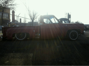
This was my daily driver and that was more or less my normal ride height. Of course all of the tuner guys at CS thought it was pretty funny (which I get). A lot of people wonder “why would you build something to drag it down the street?” My answer is, “because I can and most people can’t.”
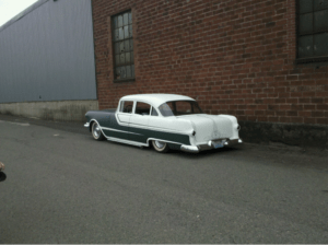
The Pontiac was a little bit classier and, while fully bagged, it didn’t “lay frame.” This car was more about the custom body work that you would never notice unless you know what a stock ’55 Pontiac is supposed to look like, specifically the rear end.
Those vehicles are long gone by now, so what have I been working on since then? Immediately after those, I bought an MS6, which you may have seen in the past. We used it at CS for product development and testing on various products, so I’m pretty sure some pics made it to the old interwebs at some point. That was my first taste of a tuner car and, while it was fun to drive, it just wasn’t my thing. So I sold it to another employee here.
Since then, I’ve played with a few 4×4 trucks, a diesel Silverado, and a ’97 F-150 which I still have and plan to build into a desert truck at some point (though that’s not yet in the project status). So what am I working on? I’m taking it back to the old school and building a minitruck — and yes, it is a Mazda but that’s just a coincidence.
A little backstory on this truck and how this project came to be: I’m probably older than most of you, but when I was a kid in the late ‘80s, minitrucks were the thing. 15” wheels were considered big wheels back then, and 195/50x15s were the standard low profile tires — quite a bit different than today. So when I was 12 in 1990, my mom went and bought this ’89 Mazda B2200 which was already lowered and had fancy red 15” wheels and a red tenneau cover. It was a pretty sweet truck by most peoples’ standards back then and IT WAS MY MOM’S! Seriously, whose mom drives a sweet minitruck?
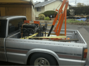
I don’t really have many old pics of it, but this was when I borrowed it from her to haul a motor for my ’63 GMC project.
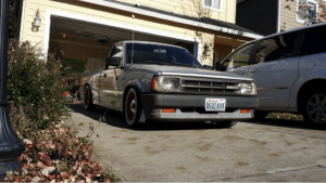
Even at 12, I loved cars. I would spend my time reading “Lowrider Magazine” or “Mini Truckin’” and drawing pictures of customized cars, so of course I was in love with the truck. I dreamt of my mom giving it to me when I turned 16 and got my license (which didn’t happen), and all of the cool stuff I would do to it. At some point when I was probably 14, the truck was stolen and wrecked which destroyed one of the wheels. You couldn’t get them anymore, so my mom put the ugly Moderns on it, which you can see in the pic above. Then later something happened to the tonneau (don’t remember what). Needless to say, time took its toll on the truck. It wasn’t the same truck anymore, but it didn’t change or take away all the time I spent daydreaming about all of the things I wanted to do to that truck as a teen.
So fast-forward 24 to 25 years. My mom was retiring and didn’t need the truck anymore. At this point, it was just a 25-year-old B2200, so it wasn’t worth much to anyone aside from me. She said if I wanted it, I could have it, so of course I jumped on it as I’d been thinking about this truck and what I would do to it for over half of my life. So what were my plans for it?
I wanted to mix keeping it how it was with doing some of the things I’d thought about over the years. So the first thing I had to do was put some red wheels on it again, as that’s how it was when I was young. However, I wanted to cross it with a bit of my preferred “old school” style, so I had to mix it up a bit. I picked up some 15” steelies with chrome center caps and had the wheels powder coated red. I also wanted wide white wall tires, but I couldn’t find the size I wanted, so I got other tires and added some Porta-walls for the wide white look. I then replaced all of the bushings and ball joints in the front end and added the new wheels and tires.
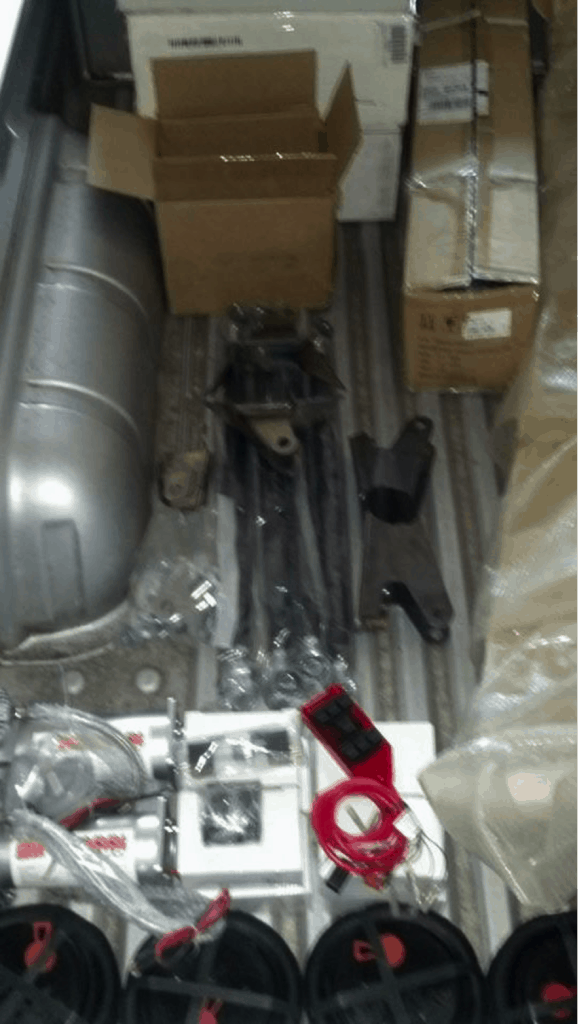
Anybody that knows me and my taste for vehicles would know that I wasn’t done at this point, so I continued to collect components for the next step. Full air ride was on its way. I got everything needed to bag it, including a complete 4-link kit for the rear. (Sorry for the blurry pic; it’s what I got.)
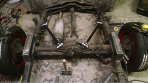
I then kind of lost motivation, so the truck largely just sat in my garage for the last couple of years. But a couple of months ago, I started working on it again. I started with notching the frame in the rear so when the suspension is aired out, the frame will sit on the ground (lay frame). I then welded in the 4-link rear suspension as seen below. I used the factory front leaf spring perch for the lower bars. (They’re there; you just can’t see them.)
Then I turned my attention to the front end. If you know anything about these trucks, you know they have a torsion bar front suspension. And if you know anything about bagging stuff, you know that isn’t the easiest starting point for airbags. Preferably you’d start with coil springs, because then you just have to remove the stock coil and put an airbag in its place (more or less). Since these are torsion bars, you have to remove most of the existing suspension and build everything you need in the front yourself. I recently finished putting the bags in the front, which is the hardest part of this project, and am now at the point where I can start making mounts and installing all of the hardware in the rear (a.k.a. the fun part).
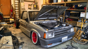
The frame is, in fact, sitting on the ground in this pic.
If you’re curious what my end goal is with this truck, I’ll fill you in: I don’t want to go full custom show truck. I plan to leave the body, faded paint and all, just as it is. I’ll also leave the big ugly mirrors and stock rear bumper, which is the first thing most minitruckers remove. Really my plan was/is to leave everything outside stock, aside from the wheels/tires, and fully bagged. Then I’ll do a custom interior with a nice sound system. The point is not a show truck; I want the stock look of the truck my mom drove for years with the ability to drag the frame down the street and throw sparks. I also plan to see if I can get another red soft tonneau cover made, so it will be a bit closer to the truck I remember as a kid — just better.
Other things I’ve considered are an NA 20b swap with a turbo 2 trans, cuz why not? Or maybe a boosted 302 swap, although that may be a bit overkill for such a small truck. It does have an automatic trans, so I don’t love that, but it works fine for low and slow. Anyhow, thanks for reading, and I hope you’ve enjoyed getting a little look at what I play with when I’m not at CS. Maybe you’ll see some updates in the future, maybe not, or maybe you’ll get a look at some of the other guys’ projects around here. Let us know what you’d like to see and we’ll see if we can accommodate.