Avoiding Clamp Failure Modes

As CorkSport works through R&D on any new part we are developing, we always take the time to consider possible failure modes. This ensures the final product has been thoroughly thought out and developed to avoid as many potential failure scenarios as possible.

Failure modes can come in many different forms. There are failure modes brought on by the product that have to be considered, failure modes brought on by assembly and packaging to consider, and failure modes brought about by the installation of the product. Often a failure mode can be a simple issue that may seem trivial until you sit back and consider the potential consequences. For that reason, clamp placement is a critical issue that can be easily overlooked during installation.

The Common Cause of Clamp Failures

When a part is installed that requires clamps, it is easy to consider only the aesthetics of the part. The initial reaction is to want the clamps to be even and silicone to be on properly, but there are a number of other potential hazards that need to be addressed when installing clamps.

The motor itself rocks back and forth which is particularly noticeable on a Mazda where the motor rocks a lot. Because the motor rocks but the engine bay does not, the clamps on your installed parts may move around and come into contact with other parts of the engine bay.

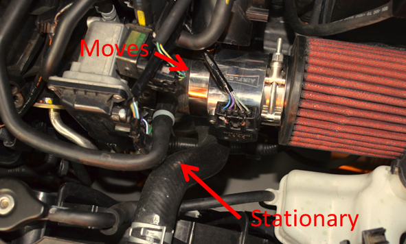
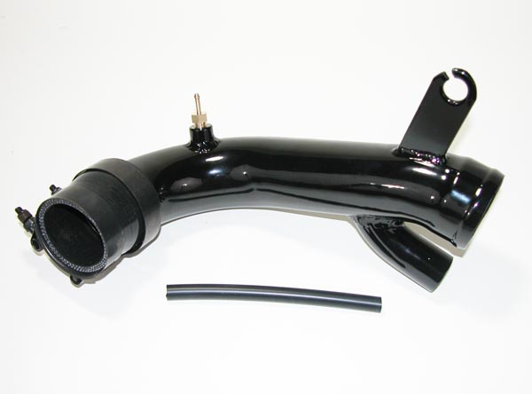
Notice the picture above. Everything looks good until you look closer. The clamp is actually touching the radiator hose which can be a potential failure point with the part. By simply rotating the clamp slightly so the bolt does not come into contact with the radiator hose, you can avoid the contact point and a possible problem with your vehicle.

Clamp placement is critically important with a front mount intercooler install because the clamps have the potential to contact a lot of parts in the engine bay and other pipes. When it comes to intakes, it is also very important to consider clamp placement because they are much closer to critical wiring. Simply flipping the orientation of the clamp can mean the difference between worn plastic and wiring harnesses or trouble free operation for years to come.

Avoiding Clamp Failures

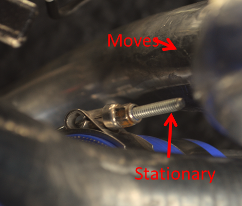
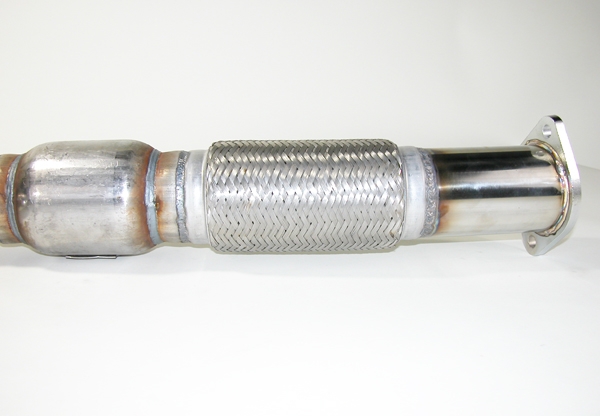
Using the picture below as an example, you can see that the clamp fits well and doesn’t touch anything, but imagine if it was tightened into the stationary object. When it moves back and forth it would eventually rub through the tape and shielding and contact the wires inside. By being aware of this, we can position the clamp so it will never contact. This is something easy to do while you are installing the part, but can be a much bigger headache down the road if it is not considered upfront.

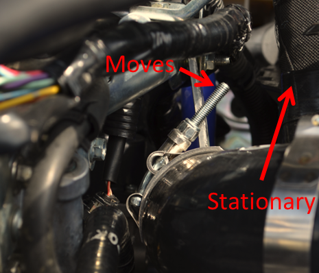
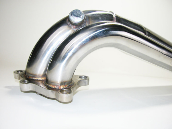
Below is another example of a clamp that is not ideally positioned. We actually have the opposite scenario here to the last example. The clamp is on a pipe that is hard mounted to the frame, while the other pipe is attached to the motor and moves. This will cause the clamp and the pipe to contact and wear against each other over time. Although both are metal, the clamp will eventually work its way through the aluminum pipe and cause a vacuum and boost leak. This means a poor running car and loss of power.

Take Time to Consider Clamp Placement During Install

Take care during your installation and avoid potential pitfalls down the road. By maintaining good clamp placement, not only will you avoid scratching the pipes, but you can avoid other potentially serious issues like boost leaks and unintentional contact with other parts in your engine bay. So remember, always keep your car safe, beautiful, and protected by maintaining good clamp placement.

Brydon-

Turbo Inlet Pipe Differences

There are some significant differences about how we designed our turbo inlet pipe compared to the other solutions offered for the DISI engine. We get a couple common questions that we thought would be worth reviewing for our readers about our design vs. the other options on the market today.

The first question we get asked most often is also the most obvious difference, which is why we chose metal over silicone. CorkSport uses a mandrel bent aluminum pipe to replace the factory plastic pipe instead of silicone. The reason we chose metal in place of silicone is to maintain a better flow through a very tight area. Metal cannot distort in shape or size and provides a smooth pipe to flow through that does not have the rougher characteristics associated with the nylon braid used in silicone.

The second question that comes up most frequently is, can a metal turbo inlet pipe transfer heat to the air rushing through the pipe at a rate that would increase the temperature of the air going into the motor? To begin with, the pipe itself is insulated from touching the turbo or block by silicone so the actual heat transferred into it is very low. It is insulated from the bracket that it bolts to by rubber and has no other contact with the engine bay other than through the air. The physical air in the engine bay should be the same no matter what intake you run so the turbo inlet pipe will eventually reach the same temperature.

In order to test this we ran our test car on the same day with less than 10 degrees difference between ambient air temp between tests. We put the car on the dyno and ran the car at the same load from the same rpm range at 20psi. This was about 2500 to 6500rpms. The above graph shows the difference between intake air temp and boost air temp. The intake air temp is basically outside air temp and the boost air temp is the temperature of the air entering the engine. There was basically no difference from metal to plastic telling us that the metal is not able to transfer heat any faster than the plastic to the actual air traveling into the motor.

Bottom line, during testing, the CorkSport Turbo Inlet Pipe showed a 14% improvement in flow over the stock turbo inlet pipe, resulting in improved boost levels, and customers can rest easy knowing that the aluminum piping will not affect the temperature of the air running to the motor

Brydon-

Dyno Differences and Understandings

It’s not everyday you get a dyno. Not all dynos are created equal and not all dynos read the same. After a little bit of research we decided on a Dynotech, a widely recognized chassis dynamometer. Dynotech uses a large drum of mass to measure the amount of force a car can exert on it. It takes this information and calculates the horsepower and torque of the vehicle. In order to do this calculation it also needs a tach signal. The reason for this is that the calculation is a relationship at given rpms. (HP = Torque x RPM ÷ 5252)

The true torque of a motor can only be seen at the engine as torque is a relationship of distance from the center line of the crankshaft. If the transmission was truly 1:1 you could measure this at the wheels but since most transmissions have no gears that are exactly 1:1, we chose a gear that is close to 1:1. This gear is generally 3rd or 4th. As an example the mazdaspeed 3 uses gearing of 1st 3.21, 2nd 1.91, 3rd 1.37, 4th 1.03, 5th 0.95, 6th 0.79. As you can see 4th gear is the closest to 1:1.

Dynojet

The dyno dynamics dyno we chose uses an electromagnetic force to measure power. This makes the unit smaller and more portable. It also makes the dyno able to change loads. You can literally apply a certain load and very the rpms or very the load and keep the same rpm. This is great for load based tuning and limits the need for a “Road Tune” as you can create real life conditions on a dyno.

The downfall of the dyno dynamics is that it is often called a heart breaker dyno. The actual reported numbers are some of the lowest numbers out of any dyno. This fact makes it important to understand that increases in power should always be measured in percentages. That way when you compare numbers, the percentage gained should be about the same while the increase in actual value might be less. You can see this below in the graphs.

Dyno Chart

The lower powers are with a stock Mazdaspeed3 and the higher values are with the exact same mods. The left dynojet graph shows a 30hp difference at one point . This is about a 14% increase in power. If you dyno the same modifications on the dyno dynamics and you see about 25hp difference which is also a 14% difference. Even though the dynos show a 5hp peak difference we know the modifications increased the same amount of power. This is shown in the percentage difference. Horsepower numbers can be shown to be a higher value but the percentage should always be similar. A point not missed when we recently dyno’ed a mazdaspeed3 that made almost 700whp (~+206%) on a dynojet but 580whp (~+204%) on our dyno dynamics. The percentage change was the same but peak difference was massive.

With the power of our new dyno literally at our fingertips, we have complete control over the test and the demands placed on the vehicle. Utilizing the dynotech software will allow us to evaluate the entire drive-train condition for the purpose of all-out performance development. Stay tuned for more rock solid, well engineered products that will take your Mazda to the next level.

Brydon-

Product Release! CorkSport Mazdaspeed 6 Catted Downpipe

CorkSport is happy to announce the release of our all new CorkSport Catted Downpipe for the Mazdaspeed 6! Check out the Downpipe V2 for the Mazdaspeed 6.

Mazdaspeed 6 catted downpipe

The CorkSport Mazdaspeed 6 Downpipe is designed to replace the restrictive catalyst in the stock downpipe and deliver improved exhaust flow for significant power gains and noticeable improvements in turbo response time and reduced backpressure. During initial testing, the CorkSport Mazdaspeed 6 Downpipe showed power gains of 26 horsepower and 32 ft. lbs. of torque at the wheels.

The CorkSport Mazdaspeed 6 downpipe is constructed from polished 3 inch 304 stainless steel piping for lasting corrosion resistance and reduced heat transfer to the engine bay. Unlike many downpipes on the market the CorkSport downpipe uses a unique divorced wastegate design that will reduce boost spikes and exhaust flow disturbances due to waste-gate operation.

The new catted version includes a high-flow spun metallic 200 cell catalyst and three O2 bungs to allow for the addition of EGT or other sensors. The Mazdaspeed 6 catted downpipe also includes the addition of the CorkSport Mazdaspeed 6 Racepipe, adding to the value and power customers can expect to see from the addition of this part to their vehicles.

If you have a turbocharged vehicle, adding a downpipe is one of the best modifications you can make to add power.   Our non-catted track version of the downpipe has been very popular with our speed6 customers so it only made sense to develop a catted version that daily drivers could enjoy as well.

The new optional catted downpipe is available for purchase from CorkSport’s online catalog at https://www.corksport.com/corksport-power-series-mazdaspeed-6-downpipe-en.html

Connect with us

Stay up-to-date on the latest news and product updates from CorkSport.

* indicates required

CorkSport Coilover Development Process

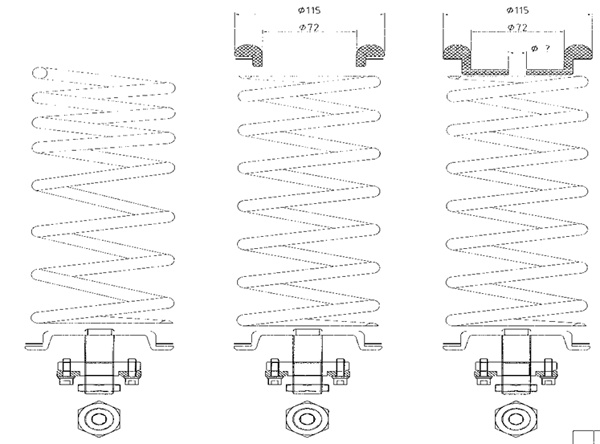
There are many features and design elements that can be incorporated into coilovers so when CorkSport decided to design new coilovers for the Mazda 3 and Mazdaspeed 3 we had to come up with priorities. We asked the Mazda community what features they wanted to see incorporated and what we came up with and will be releasing in the near future fulfills all of those wants and needs at a competitive price.

You told us you wanted inverted struts. We decided on a 45mm inverted strut body for the fronts and traditional strut bodies for the rear. There are some huge advantages to inverted struts. Inverted refers to a strut that is built upside down. The shaft that moves actually holds the gas or oil in some cases. Traditionally this is held in the lower section of the strut and moved up and down as the control arm moved up and down. The first huge advantage of inverted struts is the unsprung weight. This refers to the weight that your suspension holds. If the weight is on a portion of the suspension that moves this is referred to as sprung weight which we limited by moving the factory oil and strut body to a hard-mounted body position so the only weight that has to move is a hollow body.

The second advantage of inverted struts is side loading. With Macpherson-style struts in the front, your suspension is literally held together by the strut. By increasing the surface area on the strut tubes we increased the rigidly of the structure to make a more stable suspension, which is great if you like a good autocross day, track day or a drive through the twisties.

The rear of the Mazdaspeed 3 and Mazda 3 uses a multilink suspension meaning the rear is tied together in a way that the suspension doesn’t hold any load. There was little need to go to an inverted strut in the rear so we decided against it.

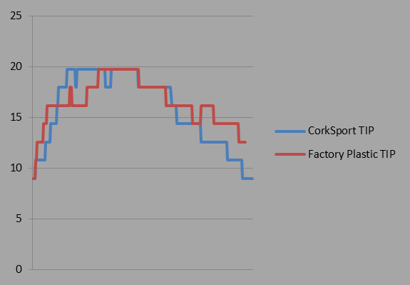
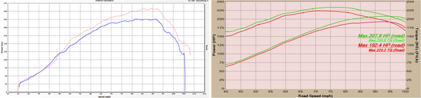
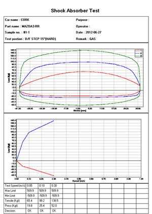
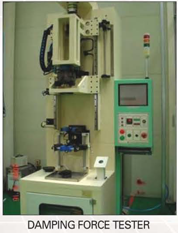
For those of you out there that need data, we have what you want.

If you have ever tried to dig up data on coilovers, you may have found that it was hard to actually get the compression and rebound on the settings. Now I am not sure if this is because it is a tightly guarded secret or most companies just don’t fully test their struts before sending them out, but we wanted to make sure that ours would be the best option on the market and outlast the factory struts in every way so we tested all of the struts for rebound and compression on professional tooling.

The data below breaks down rebound and compression into six twists of the dampener knob. They are 15-way adjustable but by showing the six major steps the data is a little easier to absorb. Now you can have the important data that no one else seems to want to share.

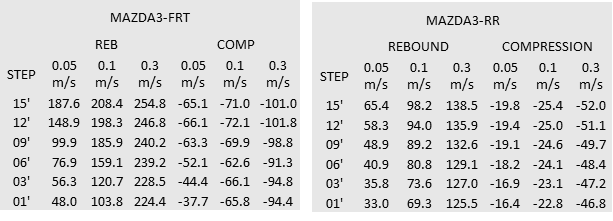
Another important part about choosing coilovers is comfort. Yes, they will be stiffer than stock but there are ways to limit the stiffness so that the system is not undrivable on harsh roads.

Up front, we added helper springs to make those little bumps and potholes take less impact on your vehicle. It can also save those nice wheels from bends and dings. The 15-way adjustable front and rear also help. With easy adjustment, you can go soft for the weekdays and stiffer for the weekends. You can also combine dampening and swaybar adjustments to make that perfect combination for your driving habits.

After you really get comfortable with the adjustments you can start changing end link preload, sway bar adjustment, strut dampening, camber settings, and toe settings.

In January, CorkSport released the front camber kit for the Mazdaspeed 3. Aside from the obvious ability to change camber, these camber plates have a lot of advantages over the factory camber plates so we decided to incorporate these into our coilover design. Using thick machined aluminum, high-grade bolts and tightly machined plates and bearings they will hold up to almost all abuse. They also get rid of the unwanted flex in the factory rubber mounts.

Now that we have covered the front coilovers we can learn a little about the rears. Because the system is a multilink rear suspension we have a separate spring and shock combo. In order to again have great ride quality with great handling we went with a progressive spring. In order to have ride height adjustability, we produced an adjustment device for the spring that is easily adjusted with an Allen wrench from the bottom of the spring.

The rear shocks are 15-way adjustable just like the fronts and can be adjusted in length to match any setup of the coilover springs. We have also accommodated for the differences between the Gen1 and Gen2 struts so everyone can enjoy these coilovers. For those people who like a little more camber in the rear, you don’t have to worry because we are currently in the development of camber adjusters for the rear.

Even at the lowest settings, we were able to dial camber into factory spec but some of us like more adjustments to their suspension settings. Soon CorkSport will release our camber adjustments for the rear. There will be another blog on camber coming soon.

We are in the final stages of testing on the coilovers and will be announcing the release soon! To be included on our pre-release list for advance information on this product.