 After releasing the CorkSport Mazda 3 SkyActiv Power Series Intake, we received several questions about the differences between the SkyActiv and traditional motors. We are writing this technical post to provide some insights into the differences we have seen while testing and developing new parts for the SkyActiv engine.
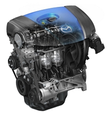
SkyActiv engine is a phrase from Mazda that denotes their direct injected, high-compression motors. This is a technology similar to how diesel engines run, in that it is direct injected and one of the many reasons the SkyActiv engine is able to get such high gas mileage.
Your average fuel injected motor runs 10.0:1 compression and fuel pressures of around 45psi whereas the SkyActiv engine runs a very high-compression of 14.0:1 and extremely high fuel pressure of up to 3000psi. Most people will think 3000psi is a typo, but I assure you it is not. 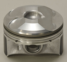
The piston pictured to the right shows how different SkyActiv pistons are compared to a conventional motor. It is a much more complex piston shape that includes a cavity in the center where the spark plug fires to provide a heat-loss reduction. Fuel is sprayed at the piston in order to prevent detonation or “knock”, allowing the engine to run leaner while making more power.
 Another big difference is that the fuel is dispersed into the air inside the cylinder. A conventional fuel injected motor will mix the fuel and air in the intake manifold or in the intake manifold runners. Because fuel normally acts as a cleaning agent for the valves, this could be seen as a negative for the SkyActiv engine design.
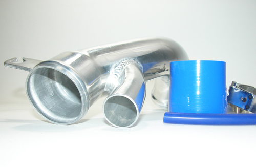
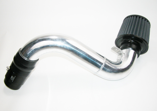
We have all seen the commercials about how the gas cleans your engine. This is true, but when we move the fuel out of the intake manifold and into the cylinders, this benefit no longer exists making it more critical to maintain the engine. 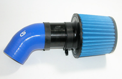 Adding a CorkSport SkyActiv intake will help with this by keeping the engine clean of dust and pollutants and the filter can be reused time and time again.
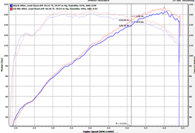
There are many great benefits to both the design and functionality of Mazda’s new SkyActiv engines. In initial testing our CX-5 saw increased torque and almost 40mpg.
We are looking forward to developing many more aftermarket performance parts to support this new technology!
Brydon-
Related SkyActive Parts
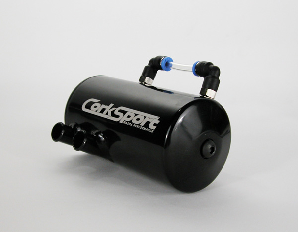
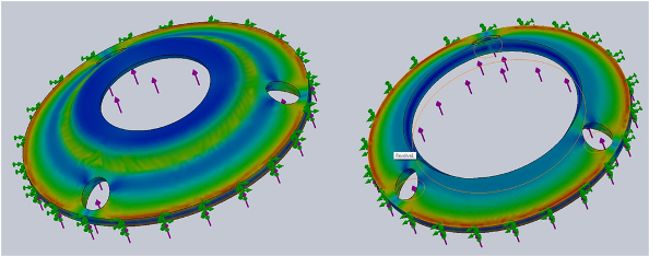
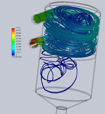 Unlike other catch cans on the market that simply expect the contaminates to fall out of the PCV vapors, our newly released oil catch can has a unique cyclonic vacuum design that forces contaminants to the walls of the can before the air can move back into the intake system. This Solidworks simulation shows how the system was designed. You can see that the air swirls around the outside of the can trapping the contaminants at the wall. This allows them to fall through a disk that is welded between two chambers used to separate the PCV vapors and the contaminants. Once the contaminants are separated you can view them with a sight tube located on the side of the catch can.
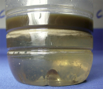 We were particularly surprised to see how much water vapor builds up in the crank case of these cars. After a few miles of driving with the catch can on our shop Mazdaspeed 3, we could really see what separates our catch can from the competition. After only 500 miles we had separated out a great deal of contaminants from the PCV system. Most of which was water vapor that had been trapped in the PCV lines and engine block. This alone should ensure that oil doesn’t break down quickly on our DISI MZR engine.
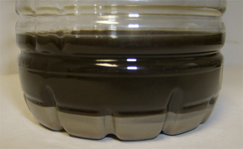 As you can see from the picture this is something you don’t want getting back into your engine. We took this sample and sent it out for particulate analysis. The results really prove that you don’t want this in your engine. Along with a large amount of oil, which can be seen, there was metal and water present in the oil. All of which we don’t want to be reburned in our engine or stuck to the back of our valves.
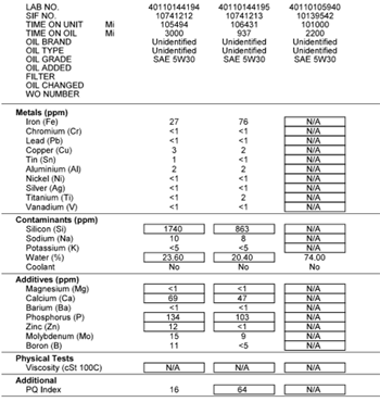 Even though it took a little longer than we expected to release this, I’m sure everyone will agree that there are certain things you want done right and somethings are worth the wait. When it comes down to it there are just some contaminants that you never want entering your motor. Most of them are listed on the sheet to the right.