Introducing, the new and improved Front Mount Intercooler Kit for the 2010-2013 Mazdaspeed 3. The CorkSport FMIC piping has been redesigned from the ground up, providing better fitment, better looks, and better performance.
What sets the CorkSport FMIC piping apart from its predecessor and the competition? The secret is in the new piping design. Let’s start with the typical “pain points” associated with a FMIC kit. When going from the TMIC to the FMIC, you are adding a considerable amount of piping and volume between the turbo and the throttle body. Most people believe this causes “turbo lag” which is true, but not nearly to the extent that the internet wants you to believe.
There are two components to the charge air that are coming from the turbocharger: pressure and volume. There are also two components to the “turbo lag” everyone curses: pressure and throttle response. Pressure is easy to explain because it’s measurable, but volume and throttle response are a bit more difficult and very much related.
Imagine walking into your local convenience store to grab a big fountain drink and without thinking you grab the biggest straw you can find. You’re not going to use the coffee stir straws right? You would never be able to get enough soda to quench your thirst! Basically, your engine is dealing with the same issue until the pressure from the turbo makes its way through the FMIC piping. This is the importance of volume! So how does this relate to the CorkSport FMIC?
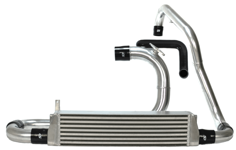
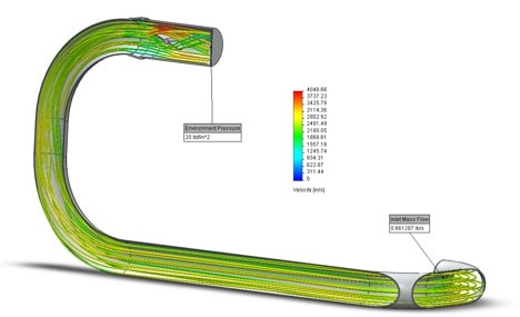
The Madaspeed FMIC piping takes volume to the next level for improved performance and drivability. Looking at Figure 2, you will notice that the last two 90-degree bends, just before the throttle body, are a bit larger in diameter than the rest of the piping. By increasing the diameter of the pipe directly in front of the throttle body, we create a large reservoir of cold air for the engine to suck in as soon as you roll into the throttle. Having this larger volume of air immediately available to the engine greatly improves drivability and throttle response because it fools the engine into thinking it has a larger intake plenum than it really does. The 3.00 inch section provides approximately 51 cubed inches of added volume over 2.50 inch piping, that’s an 18% increase.
On top of the added volume, the larger diameter piping improves the flow through the throttle body because the throttle body has a 2.75-inch inlet. You wouldn’t put a 2.5-inch turbo inlet pipe on a turbo that has a 3-inch inlet, would you? Nope, I didn’t think so. So why do that to your throttle body?
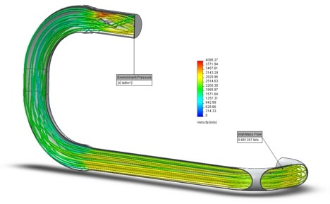
This can be seen in Figures 2 and 3 with the varying colors around and behind the throttle plate. The color graph shown with each image provides the air velocity for the different colors. In Figure 3, you can see there is more red and orange past the throttle plate when compared to Figure 2. The result of higher velocity flow is more turbulence which lowers efficiency through the throttle body.
So, if volume improves performance, then why isn’t the entire piping system 3 inches? At a certain point, more volume becomes a performance degrade. This falls back to the pressure and volume compromise. The more volume you have, the longer it takes to build pressure. Smaller diameter piping makes up the rest of the kit, so the turbo can pressurize the system quickly while the engine is using the extra volume sitting directly in front of the throttle body. By the time the extra volume is used up, the pressure has made it through the entire system. The combination of these two reduces turbo lag and improves throttle response. It’s safe to say that this is the best of both worlds.
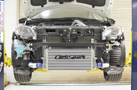
But wait there’s more! Along with new piping, we are offering a large core kit with a crash bar. The crash bar retains all the necessary OEM hookup points for the radiator core support and the OEM tow point.
The large core measures in at 23.25 inches wide, 11 inches tall, and 3 inches thick with 10mm runners for high thermal efficiency and a low-pressure drop through the core. Below, Figures 5 and 6 show the temperature and pressure drop of the small core tested with a K04 turbocharger at 15psi target.
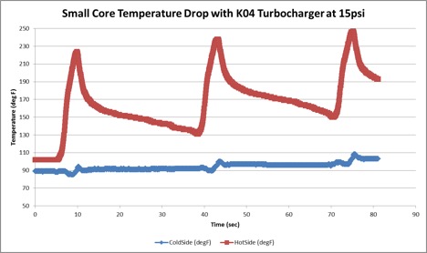
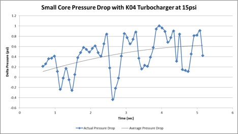
The hot side boost air temperatures can reach upward of 250 degrees Fahrenheit, but the intercooler stays at a cool 110 degrees or less. You can see the average cold side temperature is steadily increasing, but this is typical of any intercooler run after run. Combine that with an average maximum pressure drop of 0.6psi, and you have a very efficient intercooler.
That wraps up the new and improved CorkSport FMIC Kit for the 2010-2013 Mazdaspeed 3. Check it out online at corksport.com!
Connect with us
You may also like
- Mazdaspeed-3 4 Inch Complete Intake System
- How To Achieve 400 WHP In Your Mazdaspeed
- Cold Air Intake Systems Explained for your Naturally Aspirated & Turbo Mazda



Surprisingly low pressure drop, and innovative “reservoir” ahead of the throttle body. I like the CFD modeling too; thanks for sharing. I’m surprised you didn’t brag about the large elbow radii and the relative lack of hose fittings that will make this a breeze to install. Can we get figures 5 and 6 repeated for the large core as well, for comparison, or at a higher manifold pressure, when the K04 is way off its efficiency?
Solidworks Flow motion…it’s not the best and boundary condition are very important for the result but why not.
Could you post the figure on HD and a figure of the pressure drop after the reservoir ?
Any thoughts about selling just the pipes? Possibly as a upgrade from your old FMIC kit?
We do not have any plans to do so right now.