The Design – 2.5L SkyActiv-G Exhaust Header

CorkSport 2.5L SkyActiv Header

A few months ago we broke down the complicated design of the exhaust manifold found on the 2014-2018 Mazda 3 & 6 2.5L SkyActiv.  Mazda put extensive R&D into the design and packaging of the OEM header to optimize the exhaust gas pulses and overlap.  

In this blog we are going to explain some of the design features in the CorkSport 4-2-1 header and why those features are important.  

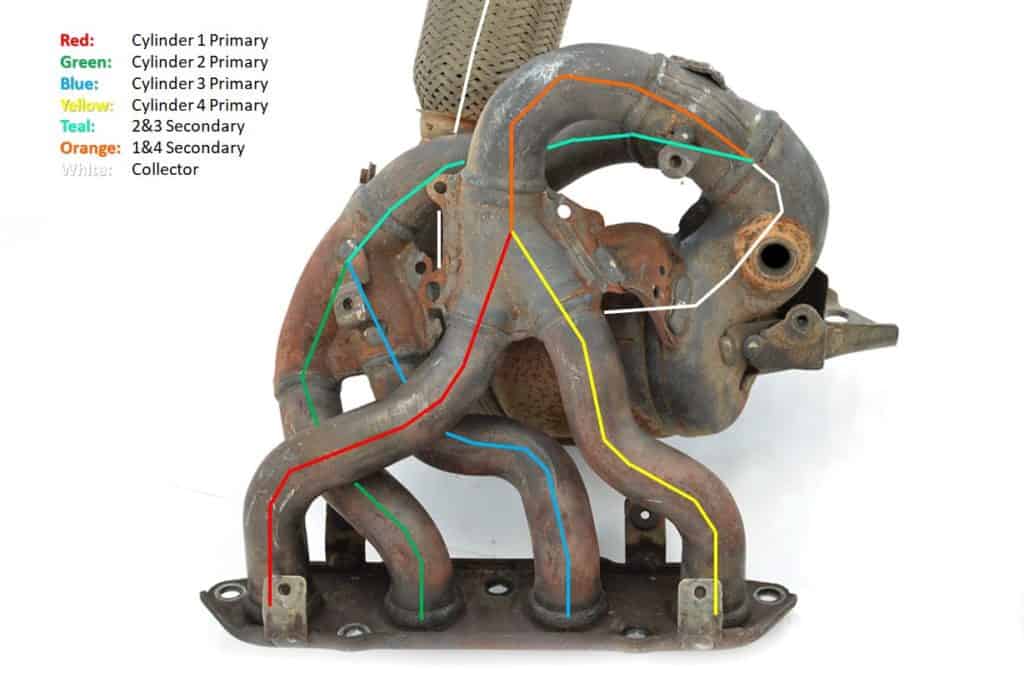
Below is a diagram showing the primary, secondary and collector routing of the OE header.  

Mazda 2.5L SkyActive Header
The OEM header for the 2.5L SkyActiv engine has a 4-2-1 design.

When designing a performance header we have to ask ourselves, “what is the goal with this performance part?” and then fulfill that goal.  With the performance header for the 2.5L SkyActiv our goal was to increase mid-range torque, retain good fitment and user installation, and improve the sound output of the exhaust system.  

CorkSport Aftermarket Exhaust Header
CorkSport 2.5L SkyActiv header design.

Immediately you’ll notice a significant difference in the design of the OEM header and the CorkSport Header.  There are three major differences:

  1. Primary, secondary, and collector diameters have been increased to promote better exhaust gas flow.
  2. Primary and secondary runner lengths have been increased to optimize power/torque lower in the RPM range.
  3. The design is two-piece to drastically improve the installation process.  

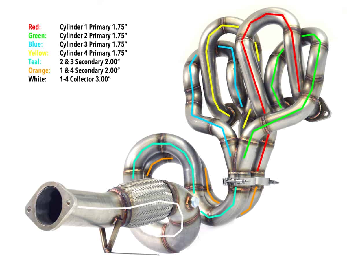
The primary runners (these are the runners that mate directly to the engine) have been increased in diameter from 1.55” to 1.75” and the secondary runners (these are the runners that combine only two cylinders before the collector) have been increased in diameter from 1.87” to 2.00”.  Both of these changes improve peak flow per cylinder throughout the RPM range. Lastly, the collector has been increased from 2.00” to 3.00” to be paired with the CorkSport 60.5mm or 80mm Cat-Back Exhaust Systems.

CorkSport Exhaust Header Installed
CorkSport Header Installed.

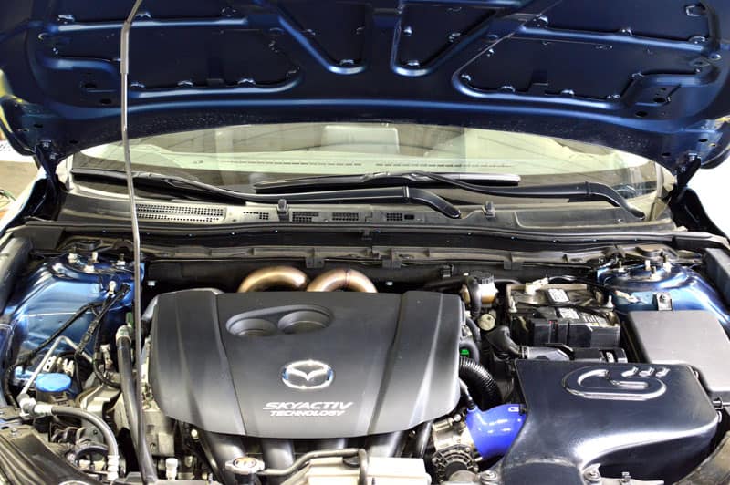
Here’s where things got a bit tricky.  Increasing the length of the primary and secondary runners forced us to be a bit creative in routing all the piping.  In order to achieve the primary runner length we wanted, we had to route the piping upward first (as you can see below) then back down between the engine and firewall.  The results were better than we expected with a “Medusa” style header peeking out of the engine bay and the lengths we wanted.

It makes us grin every time we pop the hood open, we hope you love it as much as we do.  

CorkSport 2.5L Exhaust Header broken down for install.
The final design of the CorkSport 2.5L header is installed in two pieces.

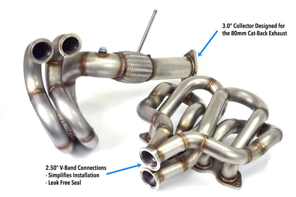
However, the complicated CorkSport design did create a new problem.  Installation! We always try to create a performance part that can be installed by the average enthusiast in their garage and this was no exception.  In a one-piece design, the header was nearly impossible to install. We went to the drawing board and realized that separating the upper and lower halves of the header was the best option.

We considered a conventional flange, gasket and hardware setup, but realized it to was far too complex in the close quarters behind the engine.  We then moved to a v-band connection that proved to be the best setup for installation, weight, and sealing ability.

That wraps up the design, next we’ll breakdown the testing and results! Let us know if you have any questions or thoughts down below.

-Barett @ CorkSport

OEM Part Breakdown: 2.5L Skyactiv-G Exhaust Header

Analyzing an OEM part is usually our first step in creating a new performance part. We’ve been looking at the Mazda 2.5l SkyActiv-G Exhaust Header, and I wanted to bring you all along for the ride. It’s surprisingly complex for an OEM manifold/header and some serious engineering went into it.

If you’ve been paying attention to the CorkSport channels, you may have seen rumors here and there of a race header for the GEN3 Mazda 3 and Mazda 6 2.5L. While I can’t say too much on that just yet, but I can give you a breakdown of the OEM exhaust header that’s hiding in the back of your engine bay.

The OEM Exhaust Header

Stock Gen 3 Mazda 3 Exhaust Header

Excuse the dirty part, as this OEM header has had a hard life! I imagine many of you have not seen the stock header as it’s in the back of your engine bay surrounded by heat shields. Taking the heat shields off gives us a glimpse of the craziness that is the stock header. Mazda has gone with a true 4-2-1 design (also known as tri-y) with an integrated catalytic converter and what appears to be equal length runners. Stay with me, I’ll explain what all that means.

SkyActiv-G Exhaust Manifold Flow Path
Exhaust Flow Path

The image above hopefully helps you visualize the 4-2-1 design. Starting at the engine, there are four exhaust ports from the head. Each exhaust port gets its own pipe, known as a “primary”. The primaries then pair together to form two “secondaries”. Finally, the two secondaries combine into one collector pipe, in this case heading directly into the catalytic converter. The three unions or “y’s” are where the tri-y name comes from. The 4-2-1 design was chosen by Mazda for a very specific reason. Check out the image below and Mazda’s explanation HERE.

Mazda SkyActiv-G Exhaust Chart
Residual gas reduction by 4-2-1 exhaust system – From Mazda.com

Essentially, using a very high compression ratio causes very high exhaust gas temperatures. If too much of this exhaust gas is leftover in the cylinders for the next combustion cycle, knocking can occur. In addition, if you have a short 4-1 header or a log-style manifold you can suck exhaust gas into a cylinder before combustion as one cylinder can be on an intake stroke while another is on an exhaust stroke (see the upper image in Mazda’s diagram).

OEM Design Efficiency

The 4-2-1 has two benefits to fight this. First, the long length means the exhaust gas takes longer to traverse the pipes, so one cylinder sucking in another’s exhaust is drastically reduced. Second, the cylinders are paired correctly to one another (1 with 4 and 2 with 3). Since the firing order is 1-3-4-2, each secondary is receiving an exhaust pulse at a regular interval. If you paired 1 with 3 for example, you would receive two pulses quickly, and then a large gap as the other two cylinders fired. This helps with exhaust scavenging as the pulse from one cylinder helps “pull” the leftover exhaust from the cylinder it’s paired with. These benefits can also be present on a long tube 4-1 if designed well but, there is a good reason why Mazda did not choose this option.


2.5L Skyactiv-G
2.5L Skyactiv-G

Typically a well-designed 4-2-1 will make more power and torque in the midrange while a well-designed 4-1 will make more power way up at the top of the RPM range. Since normal driving does not involve being at the top of the RPM range all the time, it makes sense that Mazda went with the 4-2-1. We will likely do the same as we want to retain the low knock characteristics of the 4-2-1, high midrange power & torque, and because the SkyActive 2.5L is a fairly low revving engine.

OEM Exhaust Header 4-2-1 Design

It appears that Mazda also went with close to equal length runners. This means that each primary section is the same length and each secondary section is the same length. Having equal length runners ensures the exhaust pulses are arriving at the collector (or Y) at uniform intervals.

The easiest way to explain why this is a good thing is by visualizing the entrance ramp to a highway.  When cars entering the highway follow the “zipper” method for merging, the cars currently on the highway do not need to slow down. The highway and entrance ramp merge and flow in a smooth and consistent rate. However, if a surge of cars come down the entrance ramp to merge onto the highway you will get a back-up of cars on the entrance ramp and will disrupt the flow of cars on the highway.  If the cars are exhaust gases and the highway is the exhaust pipe, you can understand why equal length can help. Again, we will adopt this strategy with the CorkSport Race Header.

So far so good then, as Mazda has put a lot of thought into making a high-quality stock header. However, as usual, there are a few areas we can improve on. That’s coming in a later blog though so you’ll have to stay tuned for more details! Let us know if you have any questions or thoughts down below.

-Daniel @ CorkSport

Collaborating with CorkSport – R&D for the Community

My name is William Dawson; for those who do not know me, I am owner/tuner at Purple Drank Tuning. In this Guest blog, I want to bring up some of the research & development I was able to contribute to with CorkSport (behind the scenes) to help bring some new performance parts to the Mazda community.

One day, many months ago, I was approached by Barett@CS to help with the tuning and development of some mystery parts CorkSport had in the works. Being who I am, I couldn’t turn down the chance to work on some new projects that could help continue to push the Mazda platform we love.  

With the pleasantries out of the way, we got down to the plan and the data.  Barett had a list of goals and how he wanted to move through the parts in testing.  The amount of data that was communicated through the first live tuning session was great. On the CorkSport in-house dyno we took their shop car to an impressive 420whp (e48 + 6 port setup) with stock manifolds, stock throttle body, and stock camshafts.

This laid the groundwork and set the stage for their product release of the CS Camshafts which gained 22whp across the curve. Along with the power increase, the camshaft upgrade also netted surprising results with turbo response.  The turbo spooled 100rpms quicker than the factory camshaft allowed. THESE ARE DROP IN RESULTS, ZERO ADJUSTMENTS! 

Mazdaspeed camshaft

Efficiency hit us with another surprise when we decided to put the CS Intake Manifold (set to re-release in early 2019) on the car and help the engine balance all of the air we have begun shoving into our test vehicle. Once again CorkSports engineering pays off with another 9whp increase and 100 rpm quicker spool up. The car lost 2-3 psi of boost which we were happy to put back in the car allowing for us to do an apples-to-apples comparison but the numbers elude me so I cannot speak to what we ended up with on that day. 


Mazdaspeed 3 intake manifold


At this point we did not know how much more we could get as the CorkSport Mazdaspeed Drop-In Turbo that was installed on the test car was producing an impressive 450whp, this did not stop us as we needed to test one more item. In comes the CS 72mm Throttle Body, this upgrade was constantly overlooked by the Mazdaspeed3 and Mazdaspeed6 community because of other attempts to get an upgraded throttle body created complications with drive by wire tables and throttle response.

Personally having a 75mm TB and not being able to enjoy the on/off throttle response and laggy part throttle was a very frustrating experience; one that even made me skeptical.  Then getting to test CorkSports product was MIND BLOWING! The test car again spooled around 100rpms sooner and throttle response was phenomenal; all with just removing 4 bolts and swapping a Throttle Body this is insanity. This team did it again, my disbelief overshadowed by pure joy that they developed a working unit and it far surpassed the factory unit in throttle response and driveability. 


Mazdaspeed3 72mm throttle body


I have known the CorkSport family for years and it does not matter what department I am working with they are always on point and pleasant to deal with regardless of the situation. Between PD and CorkSport I could not be happier to invest countless hours of hard work and R&D to allow this winning family to provide further developments and support to the Mazdaspeed 3 and Mazdaspeed 6 platforms. 


– Will Dawson (PD Tuning)


Special thanks to Will for committing his time and expertise to help CorkSport continue to grow and support the Mazdaspeed community.    – Barett @ CorkSport

Creating CorkSport Parts with 3D Scanning

While creating a new CorkSport part, we sometimes run into issues where calipers, bore gauges, and angle finders are simply not enough to get the measurements we need.  We’ve discussed how we use 3D printing in a previous blog, but today I thought I’d go over the opposite: 3D scanning.

Where 3D printing takes a CAD design from computer to physical part, 3D scanning takes a physical part and converts it into a computerized model. This is especially useful for things like intercooler piping, intake design, and even creating exterior body parts. What these components all have in common is that they are a complex, difficult to measure, shape where fitment is critical. Check out the 3D scan below from the development of our GEN2 Mazdaspeed 3 front lip. While not a perfect replica, this 3D scan information was vital for designing the CS front lip to ensure great fitment and stylish look.

At CorkSport, we do have a small 3D measuring arm that can take measurements of 3D objects and input them directly into a CAD program. The arm does this by first having a “home” position established that the arm can measure from. Then as the arm is moved around, it knows how far the tip of the arm is from the home position in x, y, and z coordinates. This is a very basic form of 3D measurement as the arm must actually touch the surfaces of the part. Mostly simple information like mounting surface locations, angles, and hole sizes can result from this arm. While not a full 3D scan, it is especially useful for things like the GEN3 Transmission Motor Mount that have mounting planes at different angles.

For intercooler piping with completely round surfaces and bends, CorkSport’s 3D measuring arm has its limitations. We typically get a full 3D scan performed on the OEM piping to give us solid locations and a great visual reference to design from. The 3D scanning arm bounces a laser off the part to determine its shape and size. Then, software that accompanies the 3D scanner stitches all the information together into a full 3D CAD model. The scans achieve great accuracy; check out the embossed writing and even texture on this OEM intercooler piping for the SkyActiv 2.5T.

From this point, we design the new CorkSport parts. In terms of intercooler piping, we analyze where the larger piping will fit to get the performance gains we want. In some cases, we can also simplify the pipe routing to get smoother airflow than the OEM piping. Having a full OEM piping scan makes this much easier as we can easily double check our measurements with the OEM parts on the car. As a result, our first 3D print can often be the final version before having metal parts made. An early design for an upgraded Mazda 6 SkyActiv 2.5T hot pipe is shown below (blue) with the OEM part scan (gray). The routing was carefully chosen to achieve our desired piping size within the constraints of the OEM engine bay.


3D scanning has a huge range of uses and we are just beginning to explore the full capabilities. Be sure to share your ideas on how we should use this technology and what new CS parts we should make with 3D scanning’s help!

-Daniel

3D Printing at CorkSport

You may have seen some funny looking parts floating around on the CS channels that did not look like the typical aluminum or steel parts you install on your Mazda or Mazdaspeed.

These plastic parts are made through 3D printing, a method we use often in R&D to really understand the ins and outs of a part. We’ve been getting a lot of questions lately on our 3D printers so I thought I’d run through what they are, how they work, and what we use them for.

3D printing is quite a simple process even though it may not seem so to start. In normal manufacturing, you start with a block of material and cut away portions until you achieve the shape you want. In 3D printing, you add material (usually plastic) layer by layer until the shape you want is achieved.

For a lot of 3D printers, including both of the CorkSport printers, you can visualize a hot glue gun attached to a robot. The robot controls where the “glue” is extruded and once the first layer is complete, the robot simply moves the object downward slightly and another layer begins. The second layer attaches to the first and you slowly gain height and shape until your part is completed.

This method is uses plastic “filament” as the material fed into the machine. Think of a spool of wire but instead of being made of copper, it’s made out of a recyclable plastic. This material is fed into the machine where it is melted and extruded like the glue in the above analogy. Other 3D printers use liquid resin that is solidified layer by layer or a powder material that gets bonded together layer by layer. The image below shows an almost empty vs brand new filament spool for our large 3D printer. To give you some scale, that is a 4 inch inlet air filter next to them– 10kg is a lot of filament!

We have two printers at CorkSport, a large Gigabot, and a small MakerBot 2X. The Gigabot can print anything that will fit in a 2-foot cube which is more than enough space for the majority of CorkSport parts. The MakerBot is much smaller, only about 9.5” by 6” by 6”. We typically use the Gigabit for most of the R&D testing and the MakerBot for making cool stuff for you all! However, the MakerBot uses a different plastic material that is stronger and more resistant to heat, allowing the parts to be tested on a running Mazda (albeit for a short time).

Barett and I use our 3D printers as tools to aid in R&D. We can take apart directly from a design in SolidWorks to a physical object extremely easily. Once we are happy with a design, it gets saved as a “mesh” made up of hundreds or thousands of tiny triangles. This is imported into a “slicer” program that does just as its name says: slices the part into layers. The part information as well as the settings for the print is exported to an SD card, which we use to upload the information to the printer.

Once we hit “print” all we have to do is wait. Smaller parts like brackets and fittings can be printed in an hour or two while large parts like manifolds or intercooler piping can take multiple days. 3D printers enable us to start a print on a Friday afternoon and leave it like this:

When we show up on Monday, the print is complete, ready for a test fit, and looking like this (Mazdaspeed 6 FMIC Piping):

I can’t express enough how much easier it is to have a physical part to test fit than to try to measure in all of the awkward angles and spaces that exist in a Mazdaspeed engine bay and hope your design will fit.

Having the capability to make a quick and inexpensive prototype to throw on a car can save countless hours and headaches down the road. This is why we use 3D printers so extensively: it makes producing great parts for you all so much easier. Some of our manufacturers even use our 3D prints to help understand the part, help with quoting, and even use them for mold/jig making. At CorkSport, our 3D printers are used almost as much as our 10mm sockets!

I’ve just scratched the surface on 3D printers, their uses, and capabilities so, if you have any questions post it down below!

-Daniel