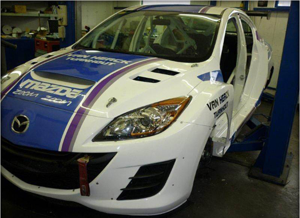
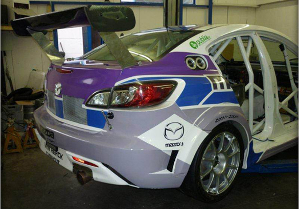
The title of this blog is really the truth, but let me explain. We have done a couple blog posts on the Van Herck Mazda 3 that is competing in the Belgian Touring Car Series over the last year.
This 2010 Mazda 3 sedan, powered by a 20B 3 rotor engine started life as a plain model silver Mazda 3 sedan powered by a 1.6 diesel engine. In today’s post we will explore the evolution of the Team Van Herck Mazda 3 and how it became the machine it is today.
The process starts with several hours of stripping the car to get a chassis ready to start work.
Next they changed the drive train layout from a front wheel drive econobox to a rear wheel drive 450 hp 20B racecar. This involves some serious surgery.
The chassis was fitted to a frame rack in order to modify the front and rear chassis. A core engine was setup to get the support frames built and the transmission mounted. You can also see the beginning of the intake penned in on the card board box.
The new framework is welded into the chassis along with the roll cage for safety. There is a huge amount of time into adding the subframe and roll cage. You can see the bolt up locations for the rear diff in the bottom of the V in the cage on the right side.
With the Mazda 3 being changed to rear wheel drive it required more space for the rear tires for the 3 rotor engine. The inner wheel liners had to be built and incorporated into the new rear suspension. The upper suspension pick up points are shown just above the new rear frame.
You may not recognize the black rear differential sub frame, that is because it is from a BMW. In this case it was used for two reasons, #1 there are tons of them available, and #2 there are plenty of options available for final drive ratios.
The rear shot through the trunk really shows the extra width given to the rear wheels.
After all of the frame work was finished up the entire chassis was painted white including the roll cage. The seat was mounted along with the pedals, steering, and wiring was started.
The rear suspension links and shock absorbers were mounted up with the new hubs.
The engine bay was coated with a layer of reflective heat insulation. Critical areas like the frame rail which is next to the exit point of the exhaust for the 20b engine. If you look at the center of the picture you can see an opening in the firewall for the exhaust to travel in. The piping exhaust travels in an enclosed channel through the right side of the chassis.
You can see the tunnel for the exhaust system along the floor of the chassis on the passenger side. More of the wiring is completed for the fuse panel and engine control.
The car uses stainless steel packed Magnaflow mufflers and v-band clamps for quick release if it needs to be changed. You can see the exit path from the exhaust tunnel. Also notice there is no floor between the frame fitted yet. It will be filled in with aluminum to enclose the car with minimal weight.
In the front of the car, the factory crash bar has been hit with a hole saw to lighten it up and filled in with pipe to keep the air passing through it from being too turbulent. The crash bar now also houses the tow strap and an alternate mount point on the right side of the car. On the hood you can see the markings for the ducting and the planned vents.
The front suspension reveals more surprises if you look close. The suspension subframe is made from aluminum and not from a Mazda 3. The knuckle is also aluminum but from a front wheel drive vehicle as you can see the splines for an axle would go in the middle of the hub. What road race car wouldn’t be complete with some huge AP racing rotors and calipers.
With the engine fitted you get a good sense of how the layout of the airbox for the intake will be. The picture gives you a good shot of the peripheral port intake manifold on the CLR built 20B. The hydraulic reservoirs are pretty easy to ID which is a must in the heat of racing when you come into the pits and you need to quickly ID items under the hood.
With the partially finished airbox you can get a sense of size of the air intake that will be fed by the hood ducting when it is completed. The metal framework above the radiator is for additional coolers which were mounted later.
With the rest of the intake installed you cannot see the engine in the Mazda 3, just some sexy purpose built carbon fiber ducting. You also get a good idea of how wide the tires are on this Mazda 3. With the widebody front fenders, they are huge.
The trunk of the Mazda 3 gets the treatment too when it comes to function. There are coolers for the rear differential and the transmissions along with the remote reservoirs for the rear shocks. If you notice the coolant tank is also set opposite the driver in the chassis to help balance out the loads.
After 1 year of hard work the Mazda 3 was out for a shakedown run at the track. The irony of the door logos is worth a laugh, it definitely is a “New Mazda”
The last touches of the Mazda 3 were completed by adding the liverly from Mazda and the Garage van Herck Raceteam.
It was reported at the first event the other teams were very surprised at the speed of the rotary powered Mazda 3.
Here are some great videos of the 20B powdered Mazda 3
Special thanks to MVdesign for the video.
2012 should be a great year for the Mazda 3 and Garage van Herck
-Derrick


Yes, that is the way to do it! Lots o cash makes lots o fun!
That’s one sweet project and the end result even sweeter. Wish Mazda would of put this car in actual production but instead they made the last Rx-8’s and killed the rotary. So sad. I’m keeping my 2010 RX8 R3 for life. It’s awesome to see such dedicated people and their hard work turn out like this. Keeping rotaries ALIVE!!!
its SOOO Beautiful. I envy it. Wish they sold an aftermarket hood like that