We’ve already mentioned briefly that we have an upgraded intercooler kit in the works for the SkyActiv 2.5T, but now it’s officially time to dive in and get into how and why a Mazda 6 upgraded intercooler kit is a good fit. To understand how to make a performance part, we first have to understand what makes the stock parts tick and where we can improve them, which is what we will be covering today!
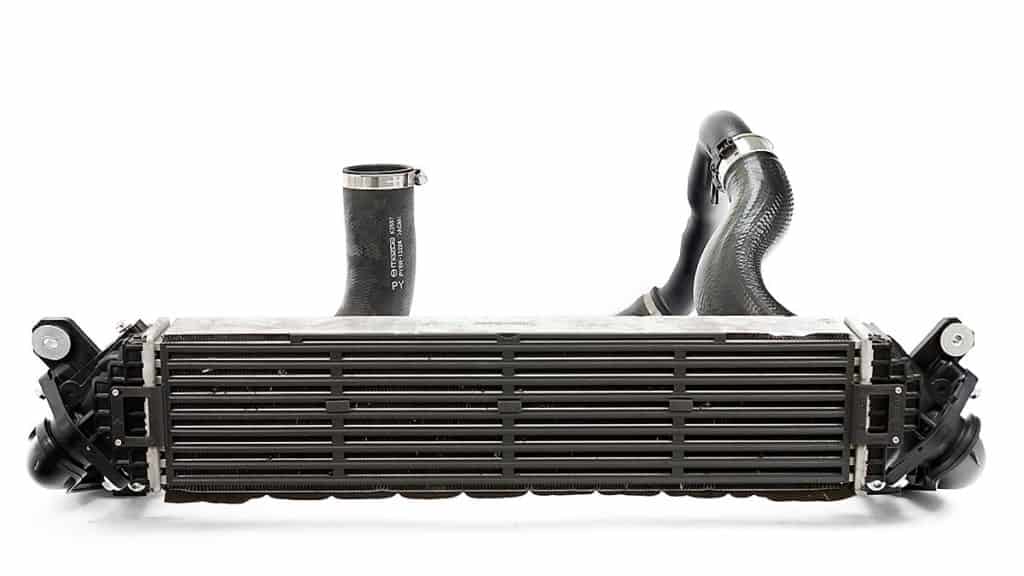
For those of you that are new to the boosted lifestyle, I feel that I should go over a few terms that will be thrown around frequently later in this blog.
-
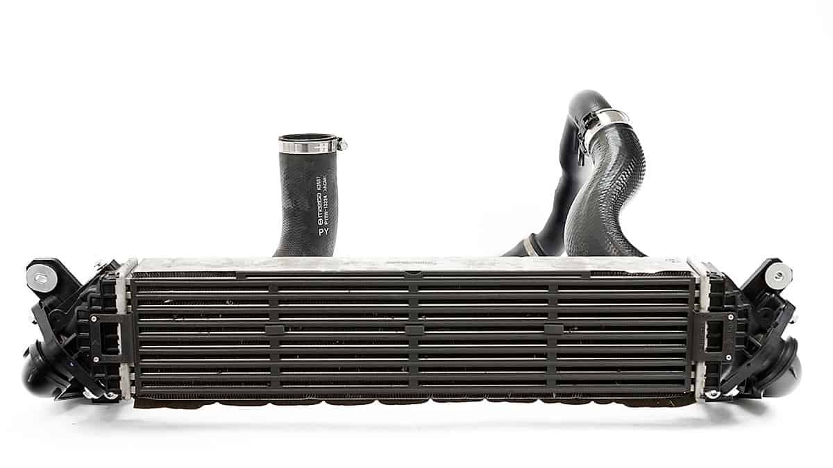
Hot Side Piping: Also known as just “hot side” or “hot pipes” this piping section carries the pressurized air (boost!) from the turbocharger to the intercooler. As it is before the intercooler, the air has not been cooled and the “hot” name is quite accurate (think 200-250°F. or even more on a turbo that’s too small). Shown above on the right side.
-
Intercooler: A basic heat exchanger. Air flows through the inside and is cooled by air flowing through the outside while you drive down the road. The same way a radiator works except with air inside instead of coolant. It is made up of three parts the “end tanks” and the “core”. The end tanks are what transfer the air from the piping to the core while the core is the actual heat exchanging portion. Shown front and center in the above image.
-
Cold Side Piping: Also known as just “cold side” or “cold pipes” this piping section carries the pressurized air from the intercooler to the engine. As it is after the intercooler, the air has been cooled to make more power. Shown above on the left side.
Now into the details…
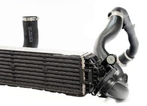
The hot side piping must make its way all the way from the rear of the engine to the front of the car. The OEM piping takes a pretty direct route, and is a decent diameter for stock piping, starting & finishing at just under 2” inner diameter. This, however, is where the good things end.
To start, the two rubber sections of the hot side are single ply. These allow for good flexibility on install and to allow for engine movement but will start to expand on higher than stock boost levels, increasing boost lag and decreasing throttle response. In the image above, the main rubber section squishes under the small weight of the upper plastic section of the hot pipe. This isn’t even the main issue with the hot side piping!
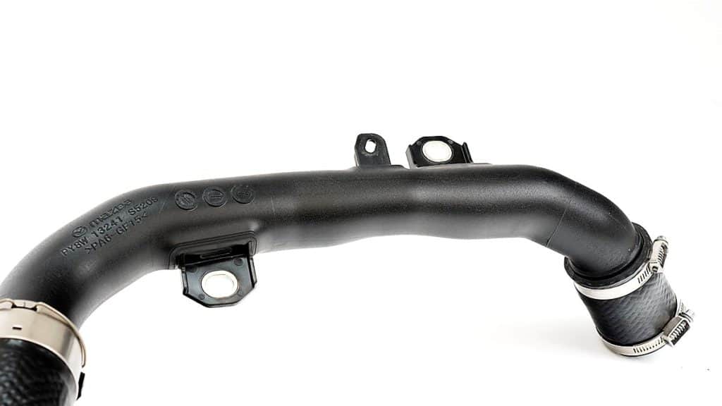
The upper plastic section of the hot side has quite a few small radius bends, and a few areas where the pipe reduces in diameter severely, affecting the maximum flow and restricting the power of your 2.5T. Check out the worst area below, it’s tiny!
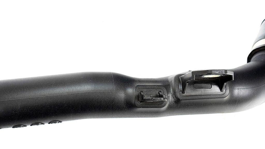
And what might be causing this reduction in diameter you may ask?
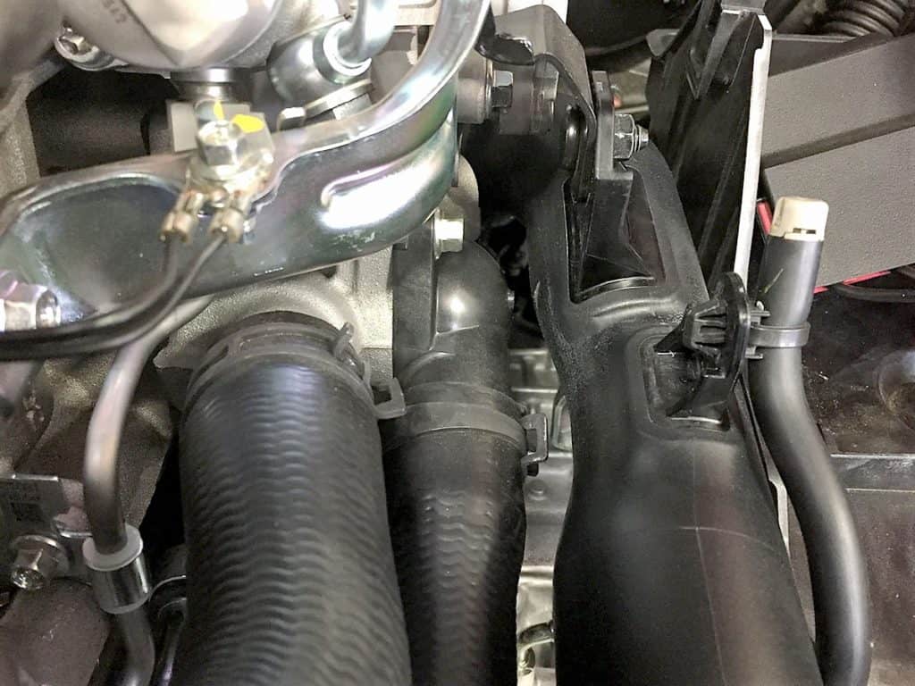
That’s right, its clearance for a hose clamp. Mazda, I’ve got to call you out on this one, couldn’t you have just rotated the clamp, and kept the diameter in the pipe? Anyways, on to the intercooler itself.
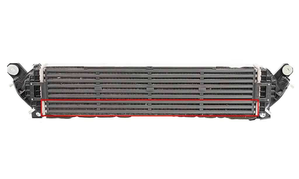
The intercooler itself isn’t too bad, a decent sized core with lots of fins to help cool as good as it can. That being said, there’s still plenty of room for improvements. First: make it bigger. The intercooler mounting could’ve been simplified to get more width, and there’s a bunch of room to go thicker. While thick is not the best for heat transfer efficiency, it will still help cool off the air better. Height is already more or less maxed out without cutting up the crash beam, but we should be able to make enough extra volume elsewhere to make a big difference.
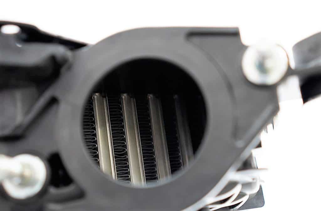
Intercoolers are a delicate balancing act between cooling efficiency and pressure drop. Cores that cool extremely well usually have a larger pressure drop (loss of pressure from inlet to outlet) and vice versa. With the high fin density of the OEM intercooler, we can expect a relatively high-pressure drop (2-4psi would be my rough guess) but pretty good cooling. From early dyno testing on the CorkSport Short Ram Intake, the intercooler does a good job cooling but loses power on back to back dyno runs. I expect that this is the intercooler “heat soaking”. Heatsoak is what happens when an intercooler is undersized or is not getting enough airflow, it heats up and is no longer able to cool the boost off, robbing you of power.
The two images above show the real Achilles heel of the OEM intercooler and what is likely causing the heatsoak issues: the end tank design. Since the charge air enters and exits the core at an upward angle, it’s being directed away from the lower runners of the core. There is a sharp angle that would be hard for the air to turn, meaning the bottom three internal runners (shown with the red box) are likely not actually doing much. So you’ve got intercooler taking up space that is likely not doing much… We aim to fix this.
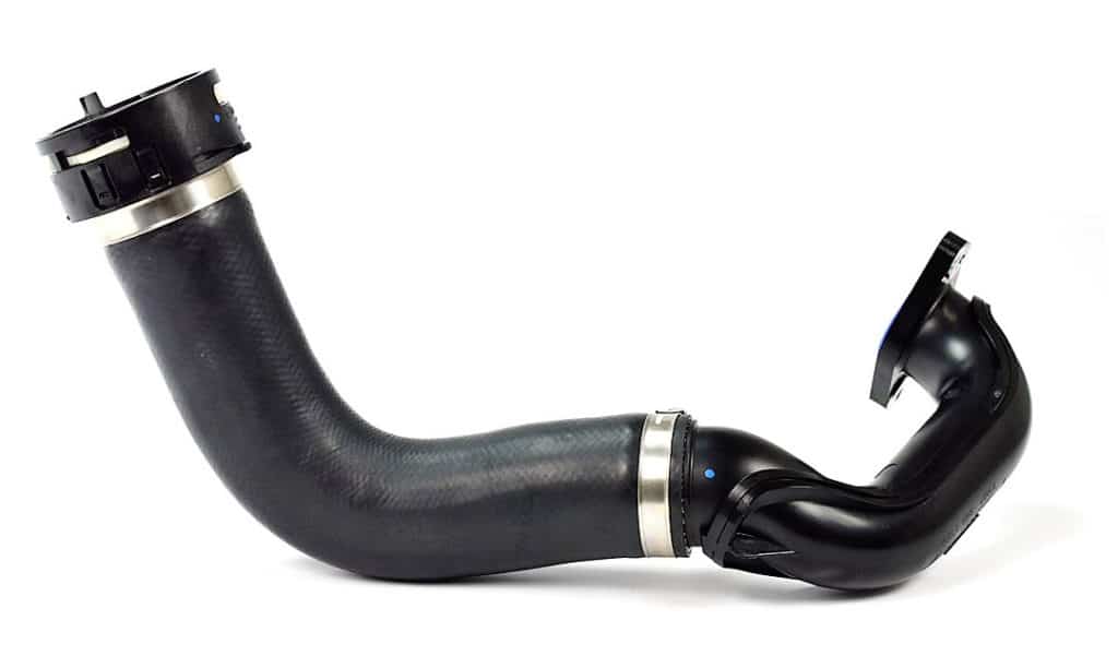
The cold side of the system is actually pretty good-inner diameter of just under 2.25” on the ends (even larger in the middle) and a short path into the throttle body. We’ve already covered the basics of it when discussing the upcoming CorkSport boost tube HERE. Like with the hot side, the rubber connector is prone to expansion under increased boost levels. While the CorkSport silicone boost tube will still be coming on its own, we plan to offer something even stiffer that is optimized for our upgraded Mazda 6 Front Mount Intercooler kit.
Much more information to come in following blogs as we’ve been busy working away on this project. Stay tuned for full details on the upcoming CorkSport FMIC kit, and if you’ve got any questions, leave them down below.


