While creating a new CorkSport part, we sometimes run into issues where calipers, bore gauges, and angle finders are simply not enough to get the measurements we need. We’ve discussed how we use 3D printing in a previous blog, but today I thought I’d go over the opposite: 3D scanning.
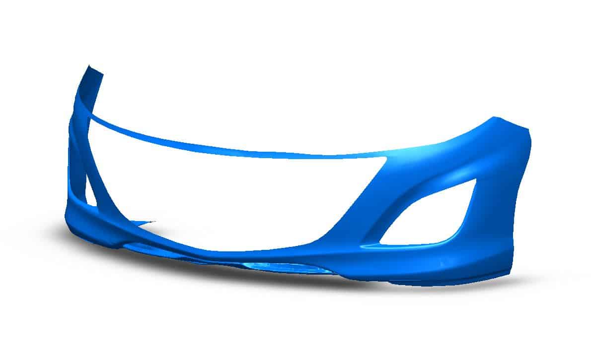
Where 3D printing takes a CAD design from computer to physical part, 3D scanning takes a physical part and converts it into a computerized model. This is especially useful for things like intercooler piping, intake design, and even creating exterior body parts. What these components all have in common is that they are a complex, difficult to measure, shape where fitment is critical. Check out the 3D scan below from the development of our GEN2 Mazdaspeed 3 front lip. While not a perfect replica, this 3D scan information was vital for designing the CS front lip to ensure great fitment and stylish look.
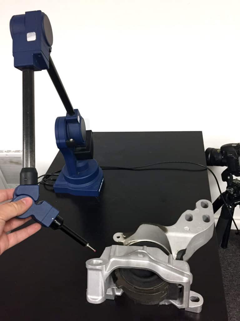
At CorkSport, we do have a small 3D measuring arm that can take measurements of 3D objects and input them directly into a CAD program. The arm does this by first having a “home” position established that the arm can measure from. Then as the arm is moved around, it knows how far the tip of the arm is from the home position in x, y, and z coordinates. This is a very basic form of 3D measurement as the arm must actually touch the surfaces of the part. Mostly simple information like mounting surface locations, angles, and hole sizes can result from this arm. While not a full 3D scan, it is especially useful for things like the GEN3 Transmission Motor Mount that have mounting planes at different angles.
For intercooler piping with completely round surfaces and bends, CorkSport’s 3D measuring arm has its limitations. We typically get a full 3D scan performed on the OEM piping to give us solid locations and a great visual reference to design from. The 3D scanning arm bounces a laser off the part to determine its shape and size. Then, software that accompanies the 3D scanner stitches all the information together into a full 3D CAD model. The scans achieve great accuracy; check out the embossed writing and even texture on this OEM intercooler piping for the SkyActiv 2.5T.
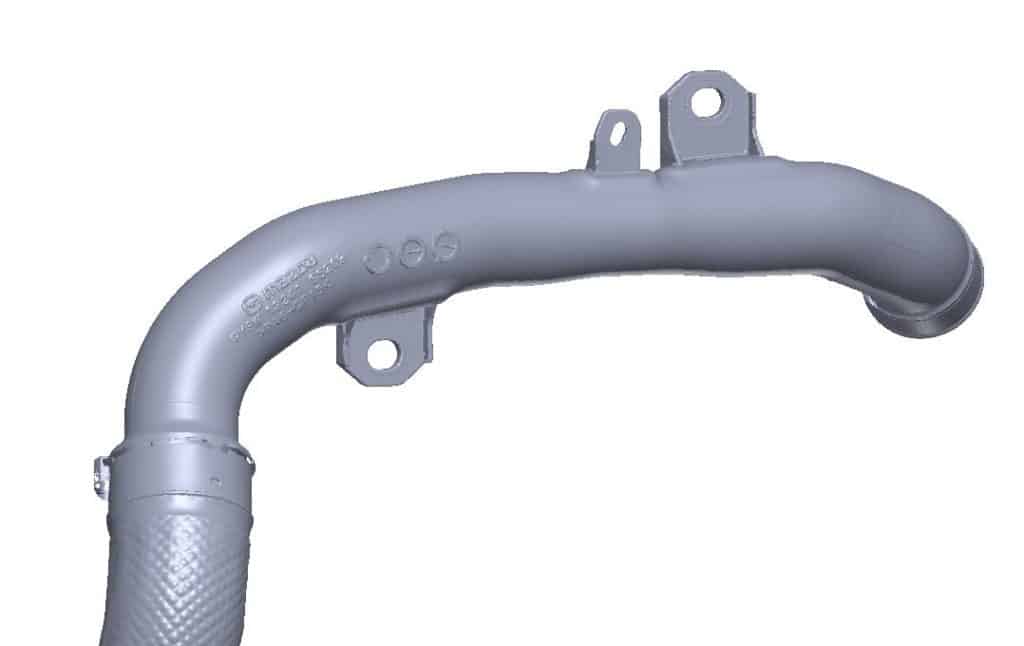
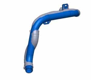
From this point, we design the new CorkSport parts. In terms of intercooler piping, we analyze where the larger piping will fit to get the performance gains we want. In some cases, we can also simplify the pipe routing to get smoother airflow than the OEM piping. Having a full OEM piping scan makes this much easier as we can easily double check our measurements with the OEM parts on the car. As a result, our first 3D print can often be the final version before having metal parts made. An early design for an upgraded Mazda 6 SkyActiv 2.5T hot pipe is shown below (blue) with the OEM part scan (gray). The routing was carefully chosen to achieve our desired piping size within the constraints of the OEM engine bay.
