
One of the most difficult development hurdles for any manufacturer of aftermarket parts is using the right design tools for the job. I’m prefer working in 3D Computer Aided Design (CAD) and Computer Aided Machining (CAM) systems and for me, it’s much easier to design up a product in the computer and be ready to go to production shortly thereafter than it is to fabricate something and then effectively reverse engineer the design into drawings and fixtures for the machine shop, tubing house and other fabrication vendors. But that requires that we start with some knowledge of where things are at on the vehicle in three dimensional space so we have a layout to work from.
Getting a good starting point to work from requires either a manufacturers computer model or skilled reverse engineering to generate that layout. There are a few ways to accomplish this -have ins with the factory and engineers at Mazda (which we have had for some time and are always dedicated to further developing), have the right tools to accurately and repeatably pull the information from the car into the CAD environment or by fabricating a working design and trying to refine that once it is complete. The difficulty of the latter method is that once you have a fabricated working design at hand, I find it a bit more difficult to think outside of the box or consider scrapping your hard work for a better design. Quick development turnaround time and being able to save multiple configurations of a design without cannibalizing the original by using CAD software makes thinking outside of the box a reality.
So what do we start with and where do we go when developing a product line?
Factory CAD Model Data
Having good connections and access to factory vehicle model content is, depending on manufacturer either extremely difficult or well facilitated through on board tech transfer programs. We’ll be gathering existing model data and comparing it to the vehicles we have in house for verification. In addition to this we’re hoping to broaden our relationship with Mazda to start gathering other CAD data where required to develop new and innovative products.
3D Digitizing Equipment
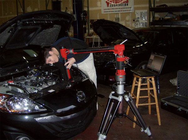
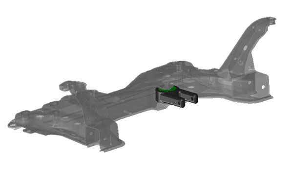
We recently had the opportunity to utilize some cutting edge technology for laying out future development on our 2010 MazdaSpeed3. Calling on Chris Jundt & Leta Holt at Hexagon Metrology, we worked with a Romer Infinite 2.0 Portable 4-Axis Coordinate Measuring Machine to digitize a number of areas on the Speed3 so that we can get a substantial boost in the return on our time invested in developing chassis bracing, molded fiberglass and rubber/urethane functional styling components and induction systems accessories. Consisting of a carbon fiber armature linked together by four extremely high resolution and accuracy Heidenhain Rotary Encoders and ending with a spherical ruby stylus, the Infinite 2.0 can map any elements that exist in an up to 4-12′ sphere (depending on model) to an extremely high accuracy and repeatability. This was just what our development for the 2010 MS3 needed. Our time mapping out the unibody and chassis components went quickly. We gathered data points on all of the rear hatch mount points and chassis bracing configurations that we had already mocked up into functional prototypes. When items were out of reach, we used the arm to generate a repeatable coordinate system which allowed us to move the arm and later stitch the two files back together seamlessly.
Using these technologies gives us the opportunity to develop a variety of improved designs as well expand our product market. And not only that, but it’s a lot of fun to be able to design parts as fluidly as you can sketch and erase on a chalkboard without consuming any raw materials until you’re satisfied with the results.
We’ll discuss more about how these technologies are assisting us in our upcoming blogs on chassis bracing solutions and R&D.
– Jason